|
December 1966 Popular Electronics
 Table of Contents Table of Contents
Wax nostalgic about and learn from the history of early electronics. See articles
from
Popular Electronics,
published October 1954 - April 1985. All copyrights are hereby acknowledged.
|
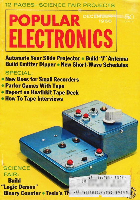
I found this Bridge
Circuit Quiz in my stack of vintage Popular Electronics magazines. I just ordered another batch of
Popular Electronics on eBay,
so that will provide a dozen or so more quizzes. Your challenge here, compliments
of Robert P. Balin, is to decide what the main function of each type of bridge
circuit is. Most bridge circuits are designed such that a component of unknown value
is inserted into one of its four branches, and then one or more variable components
of known values are adjusted to balance the bridge and thereby create a minimum
(null) between opposite (circuit-wise) nodes. Admittedly, I did not fare well, but
it is because I do not recall having the names associated with many of these
bridge circuits.
Of course nearly everyone is familiar with the Wheatstone, Kelvin, and Wien bridges.
Hyperlinks are provided to information on the bridge circuit theory. I could not
find any specific page for Mr. Resonance's bridge, but interestingly many of
the pages Google returns has to do with the
Tacoma Narrows Bridge (Galloping Gertie) self-destruction due
to resonance.
Bridge Circuit Quiz
By Robert P. Balin
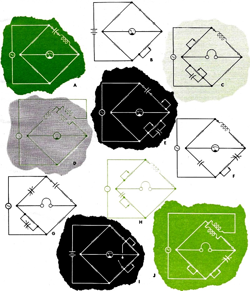
 Most electronic technicians are familiar
with the widely used Wheatstone bridge. But many are not so familiar with other
types of bridges commonly used in the laboratory for measurement of impedance-resistive,
reactive, inductive, or capacitive - at frequencies well up into the UHF band. Bridges
employ the so-called null method to measure an unknown quantity, either directly
or by computation. In the latter case, values of some of the fixed and adjustable
components in the bridge are substituted in an applicable equation, which is then
solved for the unknown quantity. See how many circuits (A-J) you can identify by
name (1-10). Most electronic technicians are familiar
with the widely used Wheatstone bridge. But many are not so familiar with other
types of bridges commonly used in the laboratory for measurement of impedance-resistive,
reactive, inductive, or capacitive - at frequencies well up into the UHF band. Bridges
employ the so-called null method to measure an unknown quantity, either directly
or by computation. In the latter case, values of some of the fixed and adjustable
components in the bridge are substituted in an applicable equation, which is then
solved for the unknown quantity. See how many circuits (A-J) you can identify by
name (1-10).
See answers below.
Quizzes from vintage electronics magazines such as Popular
Electronics, Electronics-World, QST, and Radio News
were published over the years - some really simple and others not so simple. Robert P. Balin
created most of the quizzes for Popular Electronics. This is a listing
of all I have posted thus far.
- RF Cafe Quiz #71:
Tech Headlines for Week of 3/13/2023
- RF Cafe Quiz #70:
Analog &
RF Filter Basics
- RF Cafe Quiz #69:
RF
Electronics Basics
- RF Cafe Quiz #68:
RF & Analog Company Mergers & Acquisitions in 2017
- RF Cafe Quiz #67:
RF & Microwave Company Name Change History
- RF Cafe Quiz #66:
Spectrum and Network Measurements
- RF Cafe Quiz #65:
Troubleshooting & Repairing Commercial Electrical Equipment
- RF Cafe Quiz #64:
Space-Time Adaptive Processing for Radar
- RF Cafe Quiz #63:
Envelope Tracking Power Amplifiers
- RF Cafe Quiz #62:
Stimson's Introduction to Airborne Radar
- RF Cafe Quiz #61:
Practical Microwave Circuits
- RF Cafe Quiz #60:
Ten Essential Skills for Electrical Engineers
- RF Cafe Quiz #59:
Microwave Circulator Design
- RF Cafe Quiz #58:
Microwave and Millimeter-Wave Electronic Packaging
- RF Cafe Quiz #57:
Frequency-Agile Antennas for Wireless Communications
- RF Cafe Quiz #56:
Tube Testers
and Electron Tube Equipment
- RF Cafe Quiz #55:
Conquer
Radio Frequency
- RF Cafe Quiz #54:
Microwave Mixer Technology and Applications
- RF Cafe Quiz #53:
Chipless RFID Reader Architecture
- RF Cafe Quiz #52:
RF and Microwave Power Amplifiers
- RF Cafe Quiz #51:
Antennas and Site Engineering for Mobile Radio Networks
- RF Cafe Quiz #50:
Microstrip Lines and Slotlines
- RF Cafe Quiz #49:
High-Frequency Integrated Circuits
- RF Cafe Quiz #48:
Introduction to Infrared and Electro-Optical Systems
- RF Cafe Quiz #47:
LCP for Microwave Packages and Modules
- RF Cafe Quiz #46:
RF, Microwave, and Millimeter-Wave Components
- RF Cafe Quiz #45:
Dielectric and Thermal Properties of Materials at Microwave Frequencies
- RF Cafe Quiz #44:
Monopulse Principles and Techniques
- RF Cafe Quiz #43:
Plasma Antennas
- RF Cafe Quiz #42: The Micro-Doppler
Effect in Radar
- RF Cafe Quiz #41: Introduction
to RF Design Using EM Simulators
- RF Cafe Quiz #40: Introduction
to Antenna Analysis Using EM Simulation
- RF Cafe Quiz #39: Emerging
Wireless Technologies and the Future Mobile Internet
- RF Cafe Quiz #38: Klystrons,
Traveling Wave Tubes, Magnetrons, Crossed-Field Amplifiers, and Gyrotrons
- RF Cafe Quiz #37: Component
Reliability for Electronic Systems
- RF Cafe Quiz #36: Advanced
RF MEMS
- RF Cafe Quiz #35: Frequency
Synthesizers: Concept to Product
- RF Cafe Quiz #34: Multi-Gigabit
Microwave and Millimeter-Wave Wireless Communications
- RF Cafe Quiz #33: Battlespace
Technologies: Network-Enabled Information Dominance
- RF Cafe Quiz #32: Modern Communications
Receiver Design and Technology
- RF Cafe Quiz #31: Quantum
Mechanics of Nanostructures
- RF Cafe Quiz #30: OFDMA System
Analysis and Design
- RF Cafe Quiz #29: Cognitive
Radar
- RF Cafe Quiz #28: Human-Centered
Information Fusion
- RF Cafe Quiz #27: Remarkable
Engineers
- RF Cafe Quiz #26: Substrate
Noise Coupling in Analog/RF Circuits
- RF Cafe Quiz #25: Component
Reliability for Electronic Systems
- RF Cafe Quiz #24: Ultra Low
Power Bioelectronics
- RF Cafe Quiz #23: Digital
Communications Basics
- RF Cafe Quiz #22: Remember
the Basics?
- RF Cafe Quiz #21: Wireless
Standards Knowledge
- RF Cafe Quiz #20: Famous First
Names
- RF Cafe Quiz #19: Basic Circuit
Theory
- RF Cafe Quiz #18: Archaic
Scientific Words & Definitions
- RF Cafe Quiz #17: Inventors &
Their Inventions
- RF Cafe Quiz #16: Antennas
- RF Cafe Quiz #15: Numerical
Constants
- RF Cafe Quiz #14: Oscillators
- RF Cafe Quiz #13: General
Knowledge
- RF Cafe Quiz #12: Electronics
Corporations Headquarters
- RF Cafe Quiz #11: Famous Inventors &
Scientists
- RF Cafe Quiz #10: A Sampling
of RF & Wireless Topics
- RF Cafe Quiz #9: A Smorgasbord
of RF Topics
- RF Cafe Quiz #8: Hallmark Decades
in Electronics
- RF Cafe Quiz #7: Radar Fundamentals
- RF Cafe Quiz #6: Wireless Communications
Fundamentals
- RF Cafe Quiz #5: Company Logo
Recognition
- RF Cafe Quiz #4: General RF
Topics
- RF Cafe Quiz #3: General RF/Microwave
Topics
- RF Cafe Quiz #2: General RF
Topics
- RF Cafe Quiz #1: General RF
Knowledge
- Vacuum Tube Quiz,
February 1961 Popular Electronics
- Kool-Keeping Kwiz, June
1970 Popular Electronics
- Find the Brightest
Bulb Quiz, April 1960 Popular Electronics
-
Where Do the Scientists Belong? - Feb 19, 1949 Saturday Evening Post
|
-
What's Your EQ? - April 1967 Radio-Electronics
-
What's Your EQ? -
March 1967 Radio-Electronics
-
What's Your EQ? - December 1964 Radio-Electronics
-
What's Your EQ? - January 1967 Radio-Electronics
-
Wanted: 50,000 Engineers - January 1953 Popular Mechanics
-
What's Your EQ? - August 1964 Radio-Electronics
- Voltage Quiz
- December 1961 Popular Electronics
-
What is It? - June 1941 Popular Science
- What Do You Know
About Resistors? - April 1974 Popular Electronics
-
What's Your EQ? - September 1963 Radio-Electronics
- Potentiometer Quiz - September
1962 Popular Electronics
-
Mathematical Bafflers - March 1965 Mechanix Illustrated
- Op Amp Quiz -
October 1968 Popular Electronics
- Electronic "A"
Quiz - April 1968 Popular Electronics
-
What's Your EQ? - May 1961 Radio-Electronics
-
Popular Science Question Bee - February 1939 Popular Science
-
What is It? - A Question Bee in Photographs - June 1941 Popular Science
-
What's Your EQ? - June 1961 Radio-Electronics
-
What's Your EQ? - June 1964 Radio-Electronics
-
What's Your EQ? - May 1964 Radio-Electronics
-
What's Your EQ? - August 1963 Radio-Electronics
-
What's Your EQ? - May 1963 Radio-Electronics
- Bridge
Function Quiz - September 1969 Radio-Electronics
-
What's Your EQ? - March 1963 Radio-Electronics
-
What's Your EQ? - February 1967 Radio-Electronics
-
Circuit Quiz - June 1966 Radio-Electronics
-
What's Your EQ? - June 1966 Radio-Electronics
- Electronics
Mathematics Quiz - June 1969 Popular Electronics
- Brightest
Light Quiz - April 1964 Popular Electronics
-
What's Your EQ? - April 1963 Radio-Electronics
- Electronics "B" Quiz
- July 1969 Popular Electronics
- Ohm's Law Quiz
- March 1969 Popular Electronics
-
Antenna Quiz - November 1962 Electronics World
- Color Code Quiz
- November 1967 Popular Electronics
- CapaciQuiz
- August 1961 Popular Electronics
- Transformer
Winding Quiz - December 1964 Popular Electronics
-
Audiophile Quiz - November 1957 Radio-electronics
- Capacitor
Function Quiz - March 1962 Popular Electronics
- Greek Alphabet
Quiz - December 1963 Popular Electronics
- Circuit
Designer's Name Quiz - July 19680 Popular Electronics
-
Sawtooth Sticklers Quiz - November 1960 Radio-Electronics
-
Elementary
Radio Quiz - December 1947 Radio-Craft
- Hi-Fi
Quiz - October 1955 Radio & Television News
- Electronics Physics
Quiz - March 1974 Popular Electronics
- A Baffling Quiz
- January 1968 Popular Electronics
- Electronics IQ
Quiz - May 1967 Popular Electronics
- Plug and Jack
Quiz - December 1967 Popular Electronics
- Electronic
Switching Quiz - October 1967 Popular Electronics
- Electronic
Angle Quiz - September 1967 Popular Electronics
- International
Electronics Quiz - July 1967 Popular Electronics
- FM Radio
Quiz - April 1950 Radio & Television News
- Bridge Circuit
Quiz -December 1966 Popular Electronics
- Diode Function
Quiz - August 1965 Popular Electronics
- Diagram Quiz,
August 1966 Popular Electronics
- Quist Quiz - November
1953 QST
- TV Trouble Quiz,
July 1966 Popular Electronics
- Electronics History Quiz,
December 1965 Popular Electronics
- Scope-Trace Quiz,
March 1965 Popular Electronics
-
Electronic
Circuit Analogy Quiz, April 1973
-
Test Your Knowledge of Semiconductors, August 1972 Popular Electronics
- Ganged Switching
Quiz, April 1972 Popular Electronics
- Lamp Brightness
Quiz, January 1969 Popular Electronics
- Lissajous
Pattern Quiz, September 1963 Popular Electronics
- Electronic
Quizoo, October 1962 Popular Electronics
- Electronic
Photo Album Quiz, March 1963 Popular Electronics
- Electronic
Alphabet Quiz, May 1963 Popular Electronics
- Quiz: Resistive?
Inductive? or Capacitive?, October 1960 Popular Electronics
- Vector-Circuit
Matching Quiz, June 1970 Popular Electronics
- Inductance
Quiz, September 1961 Popular Electronics
- RC Circuit Quiz,
June 1963 Popular Electronics
- Diode Quiz, July
1961 Popular Electronics
- Electronic
Curves Quiz, February 1963 Popular Electronics
- Electronic
Numbers Quiz, December 1962 Popular Electronics
- Energy Conversion
Quiz, April 1963 Popular Electronics
- Coil Function
Quiz, June 1962 Popular Electronics
-
Co-Inventors Quiz - January 1965 Electronics World
-
"-Tron" Teasers Quiz - October 1963 Electronics World
- Polarity Quiz
- March 1968 Popular Electronics
-
Television
I.Q. Quiz - October 1948 Radio & Television News
- Amplifier Quiz
Part I - February 1964 Popular Electronics
- Semiconductor
Quiz - February 1967 Popular Electronics
- Unknown
Frequency Quiz - September 1965 Popular Electronics
- Electronics
Metals Quiz - October 1964 Popular Electronics
- Electronics
Measurement Quiz - August 1967 Popular Electronics
- Meter-Reading
Quiz, June 1966 Popular Electronics
- Electronic
Geometry Quiz, January 1965 Popular Electronics
- Electronic
Factor Quiz, November 1966 Popular Electronics
- Electronics
Math Quiz, November 1965 Popular Electronics
- Series Circuit
Quiz, May 1966 Popular Electronics
- Electrochemistry
Quiz, March 1966 Popular Electronics
- Biz
Quiz: Test Your Sales Ability - April 1947 Radio News
- Electronic
Analogy Quiz, November 1961 Popular Electronics
- Electronic
Coupling Quiz, August 1973 Popular Electronics
- Electronics
Analogy Quiz, August 1960 Popular Electronics
- Audio Quiz, April
1955 Popular Electronics
- Electronic Unit
Quiz, May 1962 Popular Electronics
- Capacitor
Circuit Quiz, June 1968 Popular Electronics
|
Answers
1 - J The Carey Foster bridge measures capacitance in terms of mutual
conductance, and mutual conductance in terms of capacitance.
2 - H The Hay bridge measures the self-inductance of high-Q coils
(Q greater than 10), and also determines unknown frequencies.
3 - D The Heaviside bridge measures the mutual inductance of the
coils of a transformer in terms of a known self-inductance and known resistances.
4 - I The Kelvin bridge is used when extremely low resistances -
down to 0.001 ohm - are to be measured.
5 - C The Maxwell bridge measures the self-inductance of low-Q coils
(Q of 10 or less).
6 - F The Owen bridge, like the Hay and Maxwell bridges, measures
the self-inductance of coils. The main difference between the Owen and the other
two bridges is that the Owen bridge has the two adjustable components in the same
arm.
7 - A The Resonance bridge measures capacitance, inductance, and
frequency.
8 - G The Schering bridge measures capacitance in terms of a standard
capacitor and known resistances.
9 - B The Wheatstone bridge, oldest of the bridge family, is used
where accurate resistance measurements - in the range of 1 ohm to approximately
1 megohm - are to be made.
10 - E A Wien bridge is used to measure capacitance by comparison
with a standard capacitor, and inductance by comparison with a standard inductor.
Posted August 10, 2023
(updated from original
post on 6/22/2018)
|