NEETS Module 9 − Introduction to Wave− Generation and Wave−Shaping
Pages i,
1−1,
1−11,
1−21,
1−31,
1−41,
2−1,
2−11,
2−21,
2−31,
3−1,
3−11,
3−21,
3−31,
3−41,
3−51,
4−1,
4−11,
4−21,
4−31,
4−41,
4−51, Index
| - |
Matter, Energy,
and Direct Current |
| - |
Alternating Current and Transformers |
| - |
Circuit Protection, Control, and Measurement |
| - |
Electrical Conductors, Wiring Techniques,
and Schematic Reading |
| - |
Generators and Motors |
| - |
Electronic Emission, Tubes, and Power Supplies |
| - |
Solid-State Devices and Power Supplies |
| - |
Amplifiers |
| - |
Wave-Generation and Wave-Shaping Circuits |
| - |
Wave Propagation, Transmission Lines, and
Antennas |
| - |
Microwave Principles |
| - |
Modulation Principles |
| - |
Introduction to Number Systems and Logic Circuits |
| - |
- Introduction to Microelectronics |
| - |
Principles of Synchros, Servos, and Gyros |
| - |
Introduction to Test Equipment |
| - |
Radio-Frequency Communications Principles |
| - |
Radar Principles |
| - |
The Technician's Handbook, Master Glossary |
| - |
Test Methods and Practices |
| - |
Introduction to Digital Computers |
| - |
Magnetic Recording |
| - |
Introduction to Fiber Optics |
| Note: Navy Electricity and Electronics Training
Series (NEETS) content is U.S. Navy property in the public domain. |
COMPOSITION of NONSINUSOIDAL WAVES
Pure sine waves are basic wave shapes from which other wave shapes can be constructed.
Any waveform that is not a pure sine wave consists of two or more sine waves. Adding
the correct frequencies at the proper phase and amplitude will form square waves,
sawtooth waves, and other nonsinusoidal waveforms.
A waveform other than a sine wave is called a COMPLEX WAVE. You will see that
a complex wave consists of a fundamental frequency plus one or more Harmonic frequencies.
The shape of a nonsinusoidal waveform is dependent upon the type of harmonics present
as part of the waveform, their relative amplitudes, and their relative phase relationships.
In general, the steeper the sides of a waveform, that is, the more rapid its rise
and fall, the more harmonics it contains.
The sine wave which has the lowest frequency in the complex periodic wave is
referred to as the FUNDAMENTAL Frequency. The type and number of harmonics included
in the waveform are dependent upon the shape of the waveform. Harmonics have two
classifications - EVEN numbered and ODD numbered. Harmonics are always a whole number
of times higher than the fundamental frequency and are designated by an integer
(whole number). For example, the frequency twice as high as the fundamental frequency
is the SECOND Harmonic (or the first even harmonic).
View (A) of figure 4-25 compares a square wave with sine waves. Sine wave K is
the same frequency as the square wave (its fundamental frequency). If another sine
wave (L) of smaller amplitude but three times the frequency (referred to as the
third harmonic) is added to sine wave K, curve M is produced. The addition of these
two waveforms is accomplished by adding the instantaneous values of both sine waves
algebraically. Curve M is called the resultant. Notice that curve M begins to assume
the shape of a square wave. Curve M is shown again in view (B).
4-31
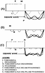
Figure 4-25. - Harmonic composition of a square wave.
As shown in view (B), when the fifth harmonic (curve N with its decreased amplitude)
is added, the sides of the new resultant (curve P) are steeper than before. In view
(C), the addition of the seventh harmonic (curve Q), which is of even smaller amplitude,
makes the sides of the composite waveform (R) still steeper. The addition of more
odd harmonics will bring the composite waveform nearer the shape of the perfect
square wave. a perfect square wave is, therefore, composed of an infinite number
of odd harmonics. In the composition of square waves, all the odd harmonics cross
the reference line in phase with the fundamental.
A sawtooth wave, shown in figure 4-26, is made up of both even and odd harmonics.
Notice that each higher harmonic is added in phase as it crosses the 0 reference
in view (A), view (B), view (C), and view (D). The resultant, shown in view (D),
closely resembles a sawtooth waveform.
4-32
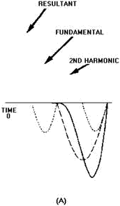
Figure 4-26A. - Composition of a sawtooth wave.
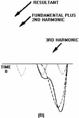
Figure 4-26B. - Composition of a sawtooth wave.
4-33
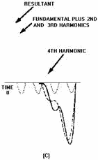
Figure 4-26C. - Composition of a sawtooth wave.
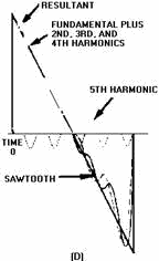
Figure 4-26D. - Composition of a sawtooth wave.
Figure 4-27 shows the composition of a peaked wave. Notice how the addition of
each odd harmonic makes the peak of the resultant higher and the sides steeper.
The phase relationship between the harmonics of the peaked wave is different from
the phase relationship of the harmonics in the composition of the square wave. In
the composition of the square wave, all the odd harmonics cross the
4-34
reference line in phase with the fundamental. In the peaked wave, harmonics such
as the third, seventh, and so forth, cross the reference line 180 degrees out of
phase with the fundamental; the fifth, ninth, and so forth, cross the reference
line in phase with the fundamental.
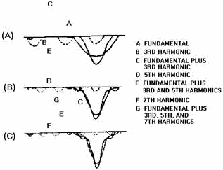
Figure 4-27. - Composition of a peaked wave.
Q15. What is the harmonic composition of a square wave?
Q16. What is the peaked wave composed of?
Q17. What is the fundamental difference between the phase relationship
of the harmonics of the square wave as compared to the harmonics of a peaked wave?
Nonsinusoidal Voltages Applied to an RC Circuit
The harmonic content of a square wave must be complete to produce a pure square
wave. If the harmonics of the square wave are not of the proper phase and amplitude
relationships, the square wave will not be pure. The term PURE, as applied to square
waves, means that the waveform must be perfectly square.
Figure 4-28 shows a pure square wave that is applied to a series-resistive circuit.
If the values of the two resistors are equal, the voltage developed across each
resistor will be equal; that is, from one pure square-wave input, two pure square
waves of a lower amplitude will be produced. The value of the resistors does not
affect the phase or amplitude relationships of the harmonics contained within the
square waves. This is true because the same opposition is offered by the resistors
to all the harmonics presented. However, if the same square wave is applied to a
series RC circuit, as shown in figure 4-29, the circuit action is not the same.
4-35
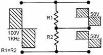
Figure 4-28. - Square wave applied to a resistive circuit.
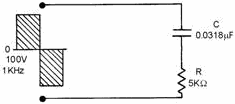
Figure 4-29. - Square wave applied to an RC circuit.
RC INTEGRATORS
The RC INTEGRATOR is used as a waveshaping network in communications, radar,
and computers. The harmonic content of the square wave is made up of odd multiples
of the fundamental frequency. Therefore SIGNIFICANT Harmonics (those that have an
effect on the circuit) as high as 50 or 60 times the fundamental frequency will
be present in the wave. The capacitor will offer a reactance (XC) of
a different magnitude to each of the harmonics

This means that the voltage drop across the capacitor for each harmonic frequency
present will not be the same. To low frequencies, the capacitor will offer a large
opposition, providing a large voltage drop across the capacitor. To high frequencies,
the reactance of the capacitor will be extremely small, causing a small voltage
drop across the capacitor. This is no different than was the case for low- and high-
pass filters (discriminators) presented in chapter 1. If the voltage component of
the harmonic is not developed across the reactance of the capacitor, it will be
developed across the resistor, if we observe Kirchhoff's voltage law. The harmonic
amplitude and phase relationship across the capacitor is not the same as that of
the original frequency input; therefore, a perfect square wave will not be produced
across the capacitor. You should remember that the reactance offered to each harmonic
frequency will cause a change in both the amplitude and phase of each of the individual
harmonic frequencies with respect to the current reference. The amount of phase
and amplitude change taking place across the capacitor depends on the XC
of the capacitor. The value of the resistance offered by the resistor must also
be considered here; it is part of the ratio of the voltage development across the
network.
The circuit in figure 4-30 will help show the relationships of R and XC
more clearly. The square wave applied to the circuit is 100 volts peak at a frequency
of 1 kilohertz. The odd harmonics will be 3 kilohertz, 5 kilohertz, 7 kilohertz,
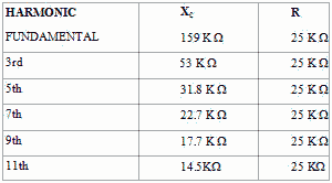
etc. Table 4-1 shows the values of XC and R offered to several
4-36
harmonics and indicates the approximate value of the cutoff frequency (XC
= R). The table clearly shows that the cutoff frequency lies between the fifth and
seventh harmonics. Between these two values, the capacitive reactance will equal
the resistance. Therefore, for all harmonic frequencies above the fifth, the majority
of the output voltage will not be developed across the output capacitor. Rather,
most of the output will be developed across R. The absence of the higher order harmonics
will cause the leading edge of the waveform developed across the capacitor to be
rounded. An example of this effect is shown in figure 4-31. If the value of the
capacitance is increased, the reactances to each harmonic frequency will be further
decreased. This means that even fewer harmonics will be developed across the capacitor.
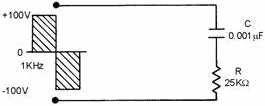
Figure 4-30. - Partial integration circuit.
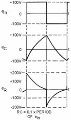
Figure 4-31. - Partial integration.
4-37
Table 4-1. - Resistive and reactive values
The harmonics not effectively developed across the capacitor must be developed
across the resistor to satisfy Kirchhoff's voltage law. Note the pattern of the
voltage waveforms across the resistor and capacitor. If the waveforms across both
the resistor and the capacitor were added graphically, the resultant would be an
exact duplication of the input square wave.
When the capacitance is increased sufficiently, full integration of the input
signal takes place in the output across the capacitor. An example of complete integration
is shown in figure 4-32 (waveform eC). This effect can be caused by significantly
decreasing the value of capacitive reactance. The same effect would take place by
increasing the value of the resistance. Integration takes place in an RC circuit
when the output is taken across the capacitor.
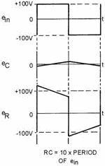
Figure 4-32. - Integration.
4-38
The amount of integration is dependent upon the values of R and C. The amount
of integration may also be dependent upon the time constant of the circuit. The
time constant of the circuit should be at least 10 TIMES GREATER than the time duration
of the input pulse for integration to occur. The value of 10 is only an approximation.
When the time constant of the circuit is 10 or more times the value of the duration
of the input pulse, the circuit is said to possess a long time constant. When the
time constant is long, the capacitor does not have the ability to charge instantly
to the value of the applied voltage. Therefore, the result is the long, sloping,
integrated waveform.
Q18. What are the requirements for an integration circuit?
Q19. Can a pure sine wave be integrated? Why?
RL INTEGRATORS
The RL circuit may also be used as an integrating circuit. An integrated waveform
may be obtained from the series RL circuit by taking the output across the resistor.
The characteristics of the inductor are such that at the first instant of time in
which voltage is applied, current flow through the inductor is minimum and the voltage
developed across it is maximum. Therefore, the value of the voltage drop across
the series resistor at that first instant must be 0 volts because there is no current
flow through it. As time passes, current begins to flow through the circuit and
voltage develops across the resistor. Since the circuit has a long time constant,
the voltage across the resistor does NOT respond to the rapid changes in voltage
of the input square wave. Therefore, the conditions for integration in an RL circuit
are a long time constant with the output taken across the resistor. These conditions
are shown in figure 4-33.
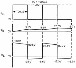
Figure 4-33. - RL integrator waveform.
Q20. What characteristic of an RL circuit allows it to act as an
integrator?
INTEGRATOR WAVEforM ANALYSIs
If either an RC or RL circuit has a time constant 10 times greater than the duration
of the input pulse, the circuits are capable of integration. Let's compute and graph
the actual waveform that would result
4-39
from a long time constant (10 times the pulse duration), a short time constant
(1/10 of the pulse duration), and a medium time constant (that time constant between
the long and the short). To accurately plot values for the capacitor output voltage,
we will use the Universal Time Constant Chart shown in figure 4-34.
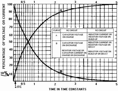
Figure 4-34. - Universal Time Constant Chart.
You already know that capacitor charge follows the shape of the curve shown in
figure 4-34. This curve may be used to determine the amount of voltage across either
component in the series RC circuit. As long as the time constant or a fractional
part of the time constant is known, the voltage across either component may be determined.
Short Time-Constant Integrator
In figure 4-35, a 100-microsecond pulse at an amplitude of 100 volts is applied
to the circuit. The circuit is composed of the, 0.01µF capacitor and the variable
resistor, R. The square wave applied is a
pure square wave. The resistance of the variable resistor is set at a value of
1,000 ohms. The time constant of the circuit is given by the equation:
TC = RC
Substituting values:
T = 1,000 · 0.01µF
T = (1 x 103) · (1 x -8)
4-40
|


