NEETS Module 9 − Introduction to Wave− Generation and Wave−Shaping
Pages i,
1−1,
1−11,
1−21,
1−31,
1−41,
2−1,
2−11,
2−21,
2−31,
3−1,
3−11,
3−21,
3−31,
3−41,
3−51,
4−1,
4−11,
4−21,
4−31,
4−41,
4−51, Index
| - |
Matter, Energy,
and Direct Current |
| - |
Alternating Current and Transformers |
| - |
Circuit Protection, Control, and Measurement |
| - |
Electrical Conductors, Wiring Techniques,
and Schematic Reading |
| - |
Generators and Motors |
| - |
Electronic Emission, Tubes, and Power Supplies |
| - |
Solid-State Devices and Power Supplies |
| - |
Amplifiers |
| - |
Wave-Generation and Wave-Shaping Circuits |
| - |
Wave Propagation, Transmission Lines, and
Antennas |
| - |
Microwave Principles |
| - |
Modulation Principles |
| - |
Introduction to Number Systems and Logic Circuits |
| - |
- Introduction to Microelectronics |
| - |
Principles of Synchros, Servos, and Gyros |
| - |
Introduction to Test Equipment |
| - |
Radio-Frequency Communications Principles |
| - |
Radar Principles |
| - |
The Technician's Handbook, Master Glossary |
| - |
Test Methods and Practices |
| - |
Introduction to Digital Computers |
| - |
Magnetic Recording |
| - |
Introduction to Fiber Optics |
| Note: Navy Electricity and Electronics Training
Series (NEETS) content is U.S. Navy property in the public domain. |
Frequency MULTIPLICATION
Frequency MULTIPLIERS are special class C amplifiers that are biased at 3 to
10 times the normal cutoff bias. They are used to generate a frequency that is a
multiple (harmonic) of a lower frequency. Such circuits are called frequency multipliers
or harmonic generators.
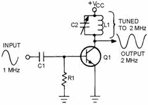
Figure 2-26 illustrates a frequency multiplier known as a Frequency DOUBLER or
SECOND Harmonic GENERATOR. As illustrated, the input is 1 megahertz and the output
is 2 megahertz, or twice the input frequency. In other words, the second harmonic
of 1 megahertz is 2 megahertz. The third harmonic (frequency tripler) would be 3
megahertz, or 3 times the input signal. The fourth harmonic (quadruplet) would be
4 megahertz, or 4 times the 1-megahertz input signal. The fourth harmonic generator
(frequency quadruplet) is normally as high in multiplication as is practical, because
at harmonics higher than the fourth, the output diminishes to a very weak output
signal.
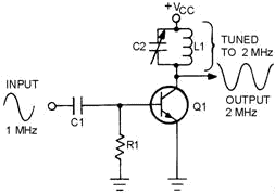
Figure 2-26. - Frequency doubler.
Frequency multipliers are operated by the pulses of collector current produced
by a class C amplifier. Although the collector current flows in pulses, the alternating
collector voltage is sinusoidal because of the action of the tank circuit. When
the output tank circuit is tuned to the required harmonic, the tank circuit acts
as a filter, accepting the desired frequency and rejecting all others.
Figure 2-27 illustrates the waveforms in a typical doubler circuit. You can see
that the pulses of collector current are the same frequency as the input signal.
These pulses of collector current energize the tank circuit and cause it to oscillate
at twice the base signal frequency. Between the pulses of collector current, the
tank circuit continues to oscillate. Therefore, the tank circuit receives a current
pulse for every other cycle of its output.
2-31
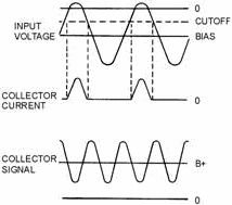
Figure 2-27. - Frequency doubler waveforms.
Buffer Amplifier
Coupling the resonant frequency from the oscillator by different coupling methods
also affects the oscillator frequency and amplitude. a BUFFER Amplifier decreases
the loading effect on the oscillator by reducing the interaction (matching impedance)
between the load and the oscillator.
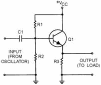
Figure 2-28 is the schematic diagram of a buffer amplifier. This circuit is a
common-collector amplifier. a common-collector amplifier has a high input impedance
and a low output impedance. Since the output of an oscillator is connected to the
high impedance of the common-collector amplifier, the buffer has little effect on
the operation of the oscillator. The output of the common-collector buffer is then
connected to an external load; therefore, the changes in the output load cannot
reflect back to the oscillator circuit. Thus, the buffer amplifier reduces interaction
between the load and the oscillator. Figure 2-29 illustrates a shunt-fed Hartley
oscillator with a buffer amplifier. This is "one-way" coupling since the oscillator
signal is coupled forward, but load changes are not coupled back to the oscillator.
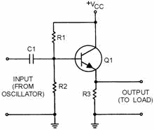
Figure 2-28. - Buffer amplifier.
2-32
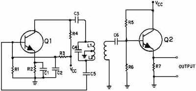
Figure 2-29. - Shunt-fed Hartley oscillator with buffer amplifier.
Q-22. What is the frequency that is twice the fundamental frequency?
Q-23. What is the purpose of the buffer amplifier?
Summary
This chapter has presented information on oscillators. The information that follows
summarizes the important points of this chapter.
WAVE GENERATORS can be classified according to the SINUSOIDAL
or NONSINUSOIDAL
waveforms produced.
SINUSOIDAL WAVE GENERATORS (oscillators) produce a sine wave
of constant amplitude and frequency. There are three ways to control the frequency
of sine-wave generators: (1) RC NetworkS, (2) LC NetworkS, and (3) CrystalS.
NONSINUSOIDAL WAVE GENERATORS (oscillators) generate complex
waveforms such as SQUARE WAVES, RECTANGULAR WAVES, SAWTOOTH WAVES, TRAPEZOIDAL WAVES,
and TRIGGERS. Nonsinusoidal wave generators are often called RELAXATION Oscillators.
A Basic Oscillator can be thought of as an amplifier that provides
itself with a signal input.

2-33
An Oscillator is a device that converts dc power to ac power
at a predetermined frequency.
The requirements for an oscillator are Amplification, Regenerative Feedback,
and a Frequency-Determining Network.
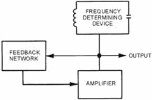
An oscillator has two stability requirements, Amplitude STABILITY and Frequency
STABILITY.
Feedback is the process of transferring energy from a high-level
point in a system to a low-level point. Feedback that aids the input signal is Regenerative
or Positive. Feedback that opposes the input signal is Degenerative or Negative.
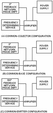
The three basic circuit configurations used for oscillators are Common
Collector,
Common Base, and Common Emitter.
In the Common-Collector configuration there is no Phase SHIFT
between input and output. It is not necessary for the feedback network to provide
a phase shift. Voltage gain is less than unity (one) and power gain is low so it
is very seldom used as an oscillator.
In the Common-Base configuration, there is no Phase SHIFT between
input and output. It is not necessary for the feedback network to provide a phase
shift. Voltage and power gain are high enough to give satisfactory operation in
an oscillator circuit.
In the Common-Emitter configuration, there is a 180-degree Phase
SHIFT between input and output. The feedback network must provide another phase
shift of 180 degrees. It has a high power gain.
2-34
The ARMSTRONG Oscillator is used to produce a sine-wave output
of constant amplitude and fairly constant frequency.
An oscillator in which dc power is supplied to the transistor through the tank
circuit, or a portion of the tank circuit, is Series FED.
An oscillator in which dc power is supplied to the transistor through a path
separate and parallel to the tank circuit is PARALLEL or Shunt FED.
The HARTLEY Oscillator is used to produce a sine-wave output
of constant amplitude and fairly constant frequency.
The COLPITTS Oscillator is used to produce a sine-wave output
of constant amplitude and fairly constant frequency within the RF range. The identifying
features of the Colpitts oscillator are the split capacitors.
The RESIsTIVE-CAPACITIVE (RC) Feedback Oscillator is used to
produce a sine- wave output of relatively constant amplitude and frequency. It uses
RC networks to produce feedback and eliminate the need for inductors in the resonant
circuit.
2-35
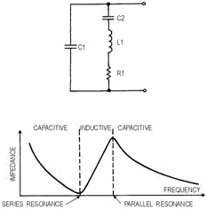
Crystal Oscillators are those oscillators that use a specially
cut crystal to control the frequency. The crystal can act as either a capacitor
or inductor, a series-tuned circuit, or a parallel-tuned circuit.
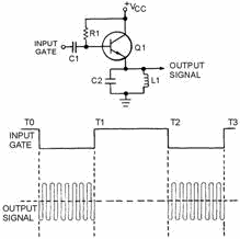
PULSED Oscillators are sinusoidal oscillators that are turned
on and off for a specific time duration. The frequency of a pulsed oscillator is
determined by both the input gating pulse and the resonant frequency of the tank
circuit.
A Harmonic is a sinusoidal wave having a frequency that is a
multiple of the fundamental frequency.
2-36
Frequency MULTIPLIERS (Harmonic GENERATORS) are special class
C amplifiers that are biased at 3 to 10 times the normal cutoff. They are used to
generate a frequency that is a multiple or harmonic of a lower frequency.
A BUFFER Amplifier decreases the loading effect on the oscillator
by reducing the interaction between the load and the oscillator.
Answers to Questions Q1. Through Q23.
A-1. Sinusoidal and nonsinusoidal.
A-2. RC, LC, and crystal.
A-3. Relaxation oscillators.
A-4. Oscillator.
A-5. Amplification, regenerative feedback, and frequency-determining
device.
A-6. Regenerative or positive.
2-37
A-7. Inductive and capacitive.
A-8. Armstrong.
A-9. Hartley.
A-10. Colpitts.
A-11. Common collector (CC), common emitter (CE), and common base
(CB).
A-12. Feedback coil. Armstrong uses a separate coil. Hartley uses
a tapped coil.
A-13. In the series-fed Hartley oscillator, dc flows through the
tank circuit.
A-14. Split capacitors.
A-15. Resistor-capacitor networks.
A-16. Because of the losses encountered in the RC networks.
A-17. Four-section.
A-18. Maximum.
A-19. Minimum.
A-20. Pulsed oscillators.
A-21. Negative.
A-22. Second harmonic.
A-23. Reduce interaction between oscillator and load.
2-38
|


