NEETS Module 9 − Introduction to Wave− Generation and Wave−Shaping
Pages i,
1−1,
1−11,
1−21,
1−31,
1−41,
2−1,
2−11,
2−21,
2−31,
3−1,
3−11,
3−21,
3−31,
3−41,
3−51,
4−1,
4−11,
4−21,
4−31,
4−41,
4−51, Index
| - |
Matter, Energy,
and Direct Current |
| - |
Alternating Current and Transformers |
| - |
Circuit Protection, Control, and Measurement |
| - |
Electrical Conductors, Wiring Techniques,
and Schematic Reading |
| - |
Generators and Motors |
| - |
Electronic Emission, Tubes, and Power Supplies |
| - |
Solid-State Devices and Power Supplies |
| - |
Amplifiers |
| - |
Wave-Generation and Wave-Shaping Circuits |
| - |
Wave Propagation, Transmission Lines, and
Antennas |
| - |
Microwave Principles |
| - |
Modulation Principles |
| - |
Introduction to Number Systems and Logic Circuits |
| - |
- Introduction to Microelectronics |
| - |
Principles of Synchros, Servos, and Gyros |
| - |
Introduction to Test Equipment |
| - |
Radio-Frequency Communications Principles |
| - |
Radar Principles |
| - |
The Technician's Handbook, Master Glossary |
| - |
Test Methods and Practices |
| - |
Introduction to Digital Computers |
| - |
Magnetic Recording |
| - |
Introduction to Fiber Optics |
| Note: Navy Electricity and Electronics Training
Series (NEETS) content is U.S. Navy property in the public domain. |
The electrical length (sweep time), which is measured from T2 to T3, can be found
by multiplying RC times the number of time constants. Refer to the Universal Time
Constant Chart (figure 3-39) again to find that 57 percent is 0.83TC. By multiplying
0.83 times R1C1, you will find that the electrical length is approximately 21 milliseconds:

The physical length (amplitude) is determined by subtracting the valley point
from the peak point. This is 9.8 volts in the example (12.8 volts - 3 volts).
For a sweep generator that produces a more linear output sawtooth waveform, refer
to the circuit in figure 3-45, view (A). R1 and C1 form the RC time constant. Notice
that the capacitor charges toward 35 volts (VE) in this circuit.
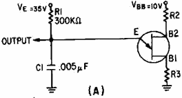
Figure 3-45A. - Improved unijunction sawtooth generator.
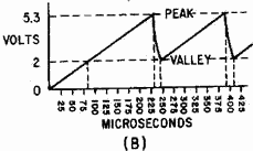
Figure 3-45B. - Improved unijunction sawtooth generator.
3-41
The output waveform is shown in figure 3-45, view (B). With a lower voltage applied
from B1 to B2, the peak and valley points are closer together. Calculating the percentage
of charge:
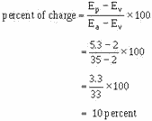
The linearity in this case is good. Using the Universal Time Constant Chart,
a 10-percent charge amounts to 0.1 time constant. The electrical length is, again,
RC times the number of time constants. With R1 at 300 kilohms and C1 at .005 microfarads,
the time constant is 1,500 microseconds. One-tenth of a time constant is equal to
150 microseconds; so the electrical length is 150 microseconds. PRT is the electrical
length plus the fall or flyback time. If C1 discharges from 5.3 volts to 2 volts
in 15 microseconds, then the PRT is 150 + 15, or 165 microseconds. The PRF is about
6 kilohertz

Some unijunction circuits are triggered to obtain a very stable PRF. One method
is to apply triggers to B2, as shown in figure 3-46. Negative triggers applied to
B2 reduce the inter-base voltage enough to cause a forward bias condition in the
emitter circuit. This cuts off the sweep and allows C1 to discharge through the
B1-to-emitter circuit. Then, C1 recharges until the next trigger arrives and C1
discharges. Circuit operation and parameters are figured in the same manner as in
the previous sawtooth circuits.
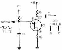
Figure 3-46. - Synchronized sawtooth generator.
3-42
Transistor SAWTOOTH GENERATOR. - The next sawtooth generator uses a conventional PNP transistor, as shown in figure 3-47, view (A). This generator
also uses an RC network, and the transistor provides the switching action.
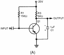
Figure 3-47A. - Transistor sawtooth generator (PNP).
The waveforms for the circuit are shown in views (B) and (C). With no input signals,
Q1 is biased near saturation by R1. The voltage across C1 is very low (-2.5 volts)
because load resistor R3 drops most of the applied voltage. The transistor must
be cut off to allow C1 to charge. To cut off Q1, a positive rectangular wave is used.

Figure 3-47B. - Transistor sawtooth generator (PNP).
3-43
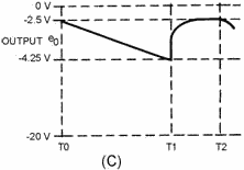
Figure 3-47C. - Transistor sawtooth generator (PNP).
Since Q1 is a PNP transistor, a positive voltage must be used to drive it to
cutoff. Figure 3-47, view (B), shows a rectangular wave input 500 microseconds long
on the positive alternation. At T0, the positive gate applied to the base of Q1
cuts off Q1. This effectively removes the transistor from the circuit (opens the
switch), and C1 charges through R3 toward 20 volts. Starting with a charge of -2.5
volts at T0, C1 charges (T0 to T1) for 500 microseconds to -4.25 volts at T1. Let's
determine the percent of charge:
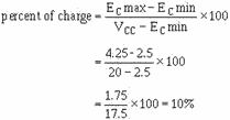
This allows nearly a linear rise of voltage across C1.
Increasing the value of R3 or C1 increases the time constant. The capacitor will
not charge to as high a voltage in the same period of time. Decreasing the width
of the gate and maintaining the same time constant also prevents the capacitor from
charging as much. With less charge on the capacitor, and the same voltage applied,
linearity has been improved. Decreasing R3 or C1 or increasing gate width decreases
linearity. Changing the applied voltage will change the charge on the capacitor.
The percentage of charge remains constant; however, it does not affect linearity.
At T1, the positive alternation of the input gate ends, and Q1 returns to a forward-bias
condition. a transistor that is near saturation has very low resistance, so C1 discharges
rapidly between T1 and T2, as shown in figure 3-47, view (C). The capacitor discharges
in less than 200 microseconds, the length of the negative alternation of the gate.
The negative gate is made longer than the discharge time of the capacitor to ensure
that the circuit has returned to its original condition.
From T1 to T2, the capacitor discharges and the circuit returns to its original
condition, ready for another positive gate to arrive. The next positive gate arrives
at T2 and the actions repeats.
3-44
The amplitude of the output sawtooth wave is equal to 1.75 volts (4.25 volts
minus 2.5 volts). The electrical length is the same as the positive alternation
of the input gate, or 500 microseconds. The PRT is
700 microseconds (500 + 200) and the PRF is 1/PRT or 1,428 hertz.
Trapezoidal Sweep Generator
Normally, oscilloscopes and synchroscopes use ELECTROSTATIC DEFLECTION and, as
the name implies, electrostatic fields move the electron beam. The need here is
for a sawtooth voltage waveform.
Another method of electron beam deflection is ELECTROMagnetic DEFLECTION. Currents
through a coil produce electromagnetic fields which position the beam of electrons.
The electromagnetic system requires a sawtooth of current which increases at a linear
rate. Because of the inherent characteristics of a coil, a sawtooth voltage does
not cause a linear increase of current. a linear increase of current requires a
TRAPEZOIDAL voltage waveform applied to a coil. This section discusses the generation
of a trapezoidal wave.
Figure 3-48 shows a trapezoidal wave. The wave consists of a sharp, almost instantaneous
jump in voltage followed by a linear rise to some peak value. The initial change
in voltage at T0 is called a JUMP or STEP. The jump is followed by a linear sawtooth
voltage rise. The time from the jump to the peak amplitude is the sum of the jump
voltage and the sawtooth peak; where the peak value occurs is the electrical length.
The peak voltage amplitude is the sum of the jump voltage and the sawtooth peak
voltage. The waveshape can be considered a combination of a rectangular wave and
a sawtooth wave.
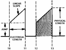
Figure 3-48. - Trapezoidal waveform.
The inductance and resistance of a coil form a series RL circuit. The voltage
drop across this inductance and resistance must be added to obtain the voltage waveform
required to produce a linear rise in current. a linear rise of current produces
a linear rise of voltage across the resistance of the coil and a constant voltage
drop across the inductance of the coil.
Assume figure 3-49, view (A), represents deflection coils. If we apply a voltage
waveshape to the circuit, which will provide a square wave across inductor L, and
a sawtooth across resistor R, then a linear current rise will result.
3-45
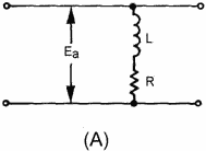
Figure 3-49A. - Series LR circuit.
View (B) of figure 3-49 shows the waveforms when Ea is a square
wave. Recall that the inductor acts as an open circuit at this first instant. Current
now starts to flow and develops a voltage across the resistor. With a square wave
applied, the voltage across the inductor starts to drop as soon as any voltage appears
across the resistor. This is due to the fact that the voltage across the inductor
and resistor must add up to the applied voltage.
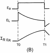
Figure 3-49B. - Series LR circuit.
With Ea being a trapezoidal voltage, as shown in figure 3-49,
view (C), the instant current flows, a voltage appears across the resistor, and
the applied voltage increases. With an increasing applied voltage, the inductor
voltage remains constant (EL) at the jump level and circuit current (IR)
rises at a linear rate from the jump voltage point. Notice that if you add the inductor
voltage (EL) and resistor voltage (ER) at any point between
times T0 and T1, the sum is the applied voltage (Ea). The key fact here
is that a trapezoidal voltage must be applied to a sweep coil to cause a linear
rise of current. The linear rise of current will cause a uniform, changing magnetic
field which, in turn, will cause an electron beam to move at a constant rate across
a CRT.
3-46
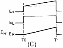
Figure 3-49C. - Series LR circuit.
There are many ways to generate a trapezoidal waveshape. For example, the rectangular
part could be generated in one circuit, the sawtooth portion in another, and the
two combined waveforms in still a third circuit. a far easier, and less complex,
way is to use an RC circuit in combination with a transistor to generate the trapezoidal
waveshape in one stage.
Figure 3-50, view (A), shows the schematic diagram of a trapezoidal generator.
The waveshapes for the circuit are shown in view (B). R1 provides forward bias for
Q1 and, without an input gate, Q1 conducts very hard (near saturation), C1 couples
the input gate signal to the base of Q1. R2, R3, and C2 form the RC network which
forms the trapezoidal wave. The output is taken across R3 and C2.
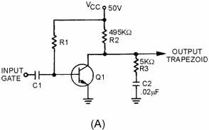
Figure 3-50A. - Trapezoidal waveform generator.
3-47
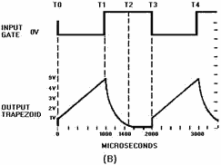
Figure 3-50B. - Trapezoidal waveform generator.
With Q1 conducting very hard, collector voltage is near 0 volts prior to the
gate being applied. The voltage across R2 is about 50 volts. This means no current
flows across R3, and C2 has no charge.
At T0, the negative alternation of the input gate is applied to the base of Q1,
driving it into cutoff. At this time the transistor is effectively removed from
the circuit. The circuit is now a series-RC network with 50 volts applied. At the
instant Q1 cuts off, 50 volts will appear across the combination of R2 and R3 (the
capacitor being a short at the first instant). The 50 volts will divide proportionally,
according to the size of the two resistors. R2 then will have 49.5 volts and R3
will have 0.5 volt. The 0.5 volt across R3 (jump resistor) is the amplitude of the
jump voltage. Since the output is taken across R3 and C2 in series, the output "jumps"
to 0.5 volt.
Observe how a trapezoidal generator differs from a sawtooth generator. If the
output were taken across the capacitor alone, the output voltage would be 0 at the
first instant. But splitting the R of the RC network so that the output is taken
across the capacitor and part of the total resistance produces the jump voltage.
Refer again to figure 3-50, view (A) and view (B). From T0 to T1, C2 begins charging
toward 50 volts through R2 and R3. The time constant for this circuit is 10 milliseconds.
If the input gate is 1,000 microseconds, the capacitor can charge for only 10 percent
of 1TC, and the sawtooth part of the trapezoidal wave will be linear.
At T1, the input gate ends and Q1 begins to conduct heavily. C2 discharges through
R3 and Q1. The time required to discharge C2 is primarily determined by the values
of R3 and C2. The minimum discharge time (in this circuit) is 500 microseconds (5KW
x .02µF x 5). At T2, the capacitor has discharged back to 0 volts and the circuit
is quiescent. It remains in this condition until T3 when another gate is applied
to the transistor.
The amplitude of the jump voltage was calculated to be 0.5 volt. The sawtooth
portion of the wave is linear because the time, T0 to T1, is only 10 percent of
the total charge time. The amplitude of the trapezoidal wave is approximately 5
volts. The electrical length is the same as the input gate length, or 1,000 microseconds.
Linearity is affected in the same manner as in the sawtooth generator. Increasing
R2 or C2, or decreasing gate width, will improve linearity. Changing the applied
voltage will increase output amplitude, but will not affect linearity.
3-48
Linearity of the trapezoidal waveform, produced by the circuit in figure 3-50,
view (A) and view (B) depends on two factors, gate length and the time constant
of the RC circuit. Recall that these are the same factors that controlled linearity
in the sawtooth generator. The formula developed earlier still remains true and
enables us to determine what effect these factors have on linearity.

An increase in gate length results in an increase in the number of time constants
and an increase in the percentage of charge that the capacitor will take on during
this time interval. As stated earlier, if the number of time constants were to exceed
0.1, linearity would decrease. The reason for a decrease in linearity is that a
greater percentage of VCC is used. The Universal Time Constant
Chart (figure 3-39) shows that the charge line begins to curve. a decrease in gate
length has the opposite effect on linearity in that it causes linearity to increase.
The reason for this increase is that a smaller number of time constants are used
and, in turn, a smaller percentage of the applied VCC is used.
Changing the value of resistance or capacitance in the circuit also affects linearity.
If the value of C2 or R3 is increased, the time is increased for 1 time constant.
An increase in the time for 1TC results in a decrease in the number of time constants
required for good linearity. As stated earlier, a decrease in the number of time
constants results in an increase in linearity (less than 0.1TC). In addition to
an increase in jump voltage (larger value of R3) and a decrease in the amplitude
(physical length) of the sawtooth produced by the circuit, electrical length remains
the same because the length of the gate was not changed.
R2 has a similar effect on linearity because it is in series with R3. As an example,
decreasing the value of R2 results in a decrease in linearity. The equation

illustrates that by decreasing R (TC = RC), TC decreases and an increase in the
number of time constants causes a decrease in linearity. Other effects are an increase
in jump voltage and an increase in the amplitude (physical length) of the sawtooth.
Changing the value of VCC does not affect linearity. Linearity
is dependent on gate length, R, and C. VCC does affect the amplitude of the
waveform and the value of jump voltage that is obtained.
Q11. For an RC circuit to produce a linear output across the capacitor,
the voltage across the capacitor may not exceed what percent of the applied voltage?
Q12. Increasing gate length in a sawtooth generator does what to
linearity?
Q13. In a sawtooth generator, why is the transistor turned on for
a longer time than the discharge time of the RC network?
Q14. What is added to a sawtooth generator to produce a trapezoidal
wave?
3-49
Summary
This chapter has presented information on waveforms and wave generators. The
information that follows summarizes the important points of this chapter.
A waveform which undergoes a pattern of changes, returns to its original pattern,
and repeats that same pattern of changes is called a PERIODIC waveform.
Each completed pattern of a waveform is called a Cycle.
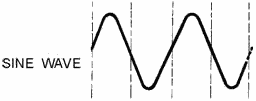
A SQUARE WAVE is identified by, two alternations equal in time
that are square in appearance. One alternation is called a PULSE. The time for one
complete cycle is called the PULSE REPETITION TIME (PRT). The number of times in
one second that the cycle repeats itself is called PULSE REPETITION RATE (PRR) or
PULSE REPETITION Frequency (PRF). The length of the pulse measured in the figure
(T0 to T1) is referred to as the PULSE WIDTH (pw). The left side of the pulse is
referred to as the LEADING EDGE and the right side as the TRAILING EDGE.

A RECTANGULAR WAVE has two alternations that are unequal in
time.

A SAWTOOTH WAVE has a linear increase in voltage followed by
a rapid decrease of voltage at the end of the waveform.
3-50
|


