Radio-Frequency Communications Principles
|
||||||||||||||||||||||||||||||||||||||||||||||||||
NEETS Module 17 − Radio−Frequency Communications Principles Pages i, 1−1, 1−11, 2−1, 2−11, 2−21, 2−31, 3−1, 3−11, 3−21, 3−31, 3−41, 4−1− to 4−10, 4−11, 5−1, 5−11, Index Chapter 4 Introduction to SATELLITE Communications Learning Objectives Upon completion of this chapter you will be able to: 1. Describe the basic operation of the two types of satellites. 2. Describe the basic components of an operational satellite system. 3. Describe the function of earth terminal equipment. 4. Describe the basic signal flow of a typical shipboard receive-only system. 5. Describe the basic signal flow of a typical shipboard transceiver system. 6. Describe the advantages of satellite communications in terms of capacity, reliability, vulnerability, and flexibility. 7. Describe the limitations of satellites in terms of power, receiver sensitivity, and availability. HIsTORY of SATELLITE Communications The first artificial satellite was placed in orbit by the Russians in 1957. That satellite, called Sputnik, signaled the beginning of an era. The United States, who was behind the Russians, made an all-out effort to catch up, and launched Score in 1958. That was the first satellite with the primary purpose of communications. The first regular satellite communications service was used by the Navy in 1960. The moon was used to bounce teletypewriter signals between Hawaii and Washington, D.C. During the early 1960s, the Navy used the moon as a medium for passing messages between ships at sea and shore stations. This method of communications proved reliable when other methods failed. Military satellite communications technology was at a low level until 1965. At that time high quality voice transmissions were conducted between a satellite and two earth stations. That was the stepping stone to the Initial Defense Communications Satellite Program (IDCSP), which will be covered later in this chapter. Experience with satellite communications has demonstrated that satellite systems can satisfy many military requirements. They are reliable, survivable, secure, and a cost effective method of telecommunications. You can easily see that satellites are the ideal, if not often the only, solution to problems of communicating with highly mobile forces. Satellites, if properly used, provide much needed options to large, fixed-ground installations. For the past fifty years, the Navy has used high-frequency (HF) transmissions as the principal method of sending messages. In the 1970s, the HF spectrum was overcrowded and "free" frequencies were at a 4-1 premium. HF jamming and electronic countermeasures (ECM) techniques became highly sophisticated during that period. As a result the need for new and advanced long-range transmission methods became apparent. Communications via satellite is a natural outgrowth of modern technology and of the continuing demand for greater capacity and higher quality in communications. In the past, the various military branches have had the resources to support their communications needs. Predicted usage indicates that large-scale improvements will have to be made to satisfy future needs of the Department of Defense. These needs will require greater capacity for long-haul communications to previously inaccessible areas. Satellite communications has the most promise for satisfying these future requirements. DEFENSE Communications SATELLITE PROGRAM (DCSP) The Defense Communications Satellite Program (DCSP) was initiated by the Secretary of Defense in 1962. Phase I of the program was given the title Initial Defense Communications Satellite Program (IDCSP). The first satellite launch occurred in June 1966 when seven experimental satellites were placed into orbit. The final launch of this program consisted of eight satellites and occurred in June 1968. DEFENSE SATELLITE Communications System (DSCS) Phase II The Phase II Defense Satellite Communications System (DSCP Phase II) has changed from an all- analog communications system to an all-digital communications system. The performance capability provided by the Phase II DSCS is limited by equipment availability. Extensive digital traffic capability has become common. You can credit this to the availability of digital modems (modulator/demodulator) and broadband equipment. Overall performance of the Phase II DSCS is a great improvement over the capabilities provided by Phase I DSCS. The Phase II satellites provide a great increase in effective radiated power and RF bandwidths. You will find these satellite configurations use wide coverage and narrow beam antennas. They provide an extensive range of communications services and capabilities. (This will be further discussed later, in this chapter.) FUNDAMENTAL SATELLITE Communications System A satellite communications system uses satellites to relay radio transmissions between earth terminals. The two types of communications satellites you will study are ACTIVE and PASSIVE. a passive satellite only reflects received radio signals back to earth. An active satellite acts as a REPEATER; it amplifies signals received and then retransmits them back to earth. This increases signal strength at the receiving terminal to a higher level than would be available from a passive satellite. A typical operational link involves an active satellite and two or more earth terminals. One station transmits to the satellite on a frequency called the UP-LINK frequency. The satellite then amplifies the signal, converts it to the DOWN-LINK frequency, and transmits it back to earth. The signal is next picked up by the receiving terminal. Figure 4-1 shows a satellite handling several combinations of links simultaneously. 4-2
Figure 4-1. - Satellite communications system. DESCRIPTION of Communications SATELLITE System The basic design of a satellite communications system depends to a great degree upon the characteristics of the orbit of the satellite. In general terms, an orbit is either elliptical or circular in shape. a special type of orbit is a SYNCHRONOUS ORBIT. In this type you will find the period (time required for one revolution) of the orbit the same as that of the earth. An orbit that is not synchronous is called ASYNCHRONOUS. a period of orbit that approaches that of the earth is called NEAR SYNCHRONOUS (subsynchronous). Orbits are discussed in more detail later in this chapter. In addition to the fundamental components shown in figure 4-1, the design of the overall system determines the complexity of the various components and the manner in which the system operates. Current satellites are capable of handling many teletypewriter (TTY) and voice circuits at the same time. Orbit Descriptions Orbits generally are described according to the physical shape of the orbit and the angle of inclination of the plane of the orbit. These terms aye discussed in the following paragraphs: PHYSICAL SHAPE. - All satellites orbit the earth in elliptical orbits. (A circle is a special case of an ellipse.) The shape of the orbit is determined by the initial launch parameters and the later deployment techniques used. PERIGEE and APOGEE are two, of the three parameters used to describe orbital data of a satellite. These are shown on figure 4-2. Perigee is the point in the orbit nearest to the center of the earth. Apogee is the point in the orbit the greatest distance from the center of the earth. Both distances are expressed in nautical miles. 4-3
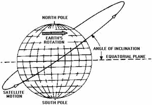
Figure 4-2. - Elliptical satellite orbit. ANGLE of INCLINATION. - The ANGLE of INCLINATION (angle between the equatorial plane of the earth and the orbital plane of the satellite) is the third parameter used to describe the orbit data of a satellite. Figure 4-3 depicts the angle of inclination between the equatorial plane and the orbital plane. Most satellites orbit the earth in orbital planes that do not coincide with the equatorial plane of the earth. a satellite orbiting in any plane not identical with the equatorial plane is in an INCLINED ORBIT.
Figure 4-3. - Inclined satellite orbit. The inclination of the orbit determines the area covered by the path of the satellite. As shown in figure 4-4, the greater the inclination, the greater the amount of surface area covered by the satellite. 4-4
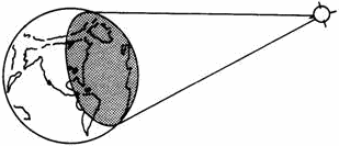
Figure 4-4. - Effect of orbit plane inclination on satellite coverage. Special TYPES of INCLINED ORBITS. - a satellite orbiting in a plane that coincides with the equatorial plane of the earth is in an EQUATORIAL ORBIT. a satellite orbiting in an inclined orbit with an angle of inclination of 90 degrees or near 90 degrees is in a POLAR ORBIT. Special TYPES of CIRCULAR ORBITS. - We stated previously that a circular orbit is a special type of elliptical orbit. You should realize a circular orbit is one in which the major and minor axis distances are equal or approximately equal. Mean height above earth, instead of perigee and apogee, is used in describing a circular orbit. While we are discussing circular orbits, you should look at some of the terms mentioned earlier in this chapter. a satellite in a circular orbit at a height of approximately 19,300 nautical miles above the earth is in a synchronous orbit. At this altitude the period of rotation of the satellite is 24 hours, the same as the rotation period of the earth. In other words, the orbit of the satellite is in sync with the rotational motion of the earth. Although inclined and polar synchronous orbits are possible, the term synchronous usually refers to a synchronous equatorial orbit. In this type of orbit, satellites appear to hover motionlessly in the sky. Figure 4-5 shows how one of these satellites can provide coverage to almost half the surface of the earth.
Figure 4-5. - Illumination from a synchronous satellite. 4-5 Three of these satellites can provide coverage over most of the earth (except for the extreme north and south polar regions). a polar projection of the global coverage of a three-satellite system is shown in figure 4-6.
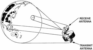
Figure 4-6. - Worldwide synchronous satellite system viewed from above the North Pole. A satellite in a circular orbit at other than 19,300 nautical miles above the earth is in a near- synchronous orbit. If the orbit is lower than 19,300 nautical miles, the period of orbit of the satellite is less than the period of orbit of the earth. The satellite then appears to be moving slowly around the earth from west to east. (This type of orbit is also called subsynchronous.) If the orbit is higher than 19,300 nautical miles, the period of orbit of the satellite is greater than the period of orbit of the earth. The satellite then appears to be moving slowly around the earth from east to west. Although inclined and polar near-synchronous orbits are possible, near synchronous implies an equatorial orbit. A satellite in a circular orbit from approximately 2,000 miles to 12,000 miles above the earth is considered to be in a MEDIUM ALTITUDE ORBIT. The period of a medium altitude satellite is considerably less than that of the earth. When you look at this altitude satellite, it appears to move rather quickly across the sky from west to east. Q1. What are the two types of communications satellites? Q2. a typical satellite communications operational link consists of a satellite and what two other components? Q3. a satellite in a synchronous orbit can cover how much of the surface of the earth? Q4. What areas of the earth are not normally covered by satellites? SATELLITE Characteristics Early communications satellites were limited in size to the diameter of the final stage of the rocket that was used for launching. Weight was determined by the thrust of the rocket motors and the maximum weight the rocket could lift into orbit. 4-6 As early as June 1960, two satellites were successfully placed in orbit by the same launch vehicle. With the development of multilaunch capability, added flexibility became available. We then had choices as to the size, weight, and number of satellites to be included in each launch. Using our multilaunch capabilities, the Defense Satellite Communications System (DSCS) has placed larger and heavier satellites in synchronous equatorial orbits. Figure 4-7 is a drawing of a DSCS satellite. It shows each pair of transmit and receive dish antennas. As you can see, a large area of the earth can be covered using only one satellite.
Figure 4-7. - DSCS satellite. Satellite Power Sources Early communications satellites were severely limited by the lack of suitable power sources. This severely limited the output power of the satellite transmitter. The only source of power available within early weight restrictions was a very inefficient panel of solar cells without battery backup. a major disadvantage of this type of power source is that the satellite has no power when it is in ECLIPSE (not in view of the sun). For continuous communications, this outage is unacceptable. A combination of solar cells and storage batteries is a better prime power source. This is a practical choice, even though the result is far from an ideal power source. About ten percent of the energy of the sunlight that strikes the solar cells is converted to electrical power. This low rate is sometimes decreased even further. You find this when the solar cells are bombarded by high-energy particles that are sometimes found in space. Early satellites had over 8,500 solar cells mounted on the surface of the satellite, which supplied about 42 watts of power. No battery backup was provided in these satellites. Newer communications satellites have about 32,000 solar cells mounted on the surface of the satellite, and they supply about 520 watts. a nickel cadmium battery is used for backup power during eclipses. Nuclear power sources have been used in space for special purposes, but their use stops there. Technology has not progressed sufficiently for nuclear power sources to be used as a power source. 4-7 Satellite Orientation Satellite orientation in space is important for continuous solar cell and antenna orientation. Since the primary source of power in most satellites is from solar cells, a maximum number of the solar cells must be exposed to the sun at all times. The satellite antenna must also be pointed at the appropriate earth terminals. Our communications satellites use what is termed spin stabilization to meet these important requirements. Spin stabilization operates on the principle that direction of the spin axis of a rotating body tends to remain fixed in space. An example of spin stabilization is the effect of the rotation of the earth in keeping its axis fixed in space. a satellite that has a spin axis parallel to the axis of the earth will maintain this position since both axes are fixed in space. Figure 4-8 illustrates the use of this principle. It depicts an equatorial orbit satellite used to keep a doughnut-shaped antenna pattern pointing toward the earth.
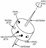
Figure 4-8. - Spin-stabilized satellite antenna pattern. Once the system is in motion, spin stabilization requires virtually no additional energy. a spin- stabilized satellite is usually constructed like a flywheel. Its heavier equipment is mounted in the same plane and as close to the outside surface as possible. After reaching its orbit, the radial jets are pulsed to start the satellite spinning. The satellite spin axis is orientated to the axis of the earth by means of small axial jets. Velocity jets are used to place the satellite in orbit position and provide velocity correction. Figure 4-9 is an example of spin stabilization.
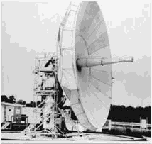
Figure 4-9. - Spin-stabilized satellite controls. 4-8 Solar cells are installed around the outside surface of a spin-stabilized satellite. This gives you a large number of solar cells exposed to the sun at all times (except when the satellite is in eclipse). The use of omnidirectional antennas causes a small part of the total radiated energy to be directed toward the earth at all times. Omnidirectional antennas radiate only a small amount of energy toward the earth. Many techniques have been tried to achieve an earth-oriented antenna system. One system developed uses spin stabilization for orientation of the satellite. It uses a stationary inner platform for mounting remote controlled antennas. The satellite is constructed in two parts with both parts having radial jets. The inner platform contains the communications antennas and the communications package. After the satellite is stabilized in space, inner radial jets spin the inner platform. The inner platform is stationary with respect to earth and is oriented to such a position that the communications antennas point continuously toward the earth. This arrangement allows the use of high-gain directional antennas that concentrate the majority of the radiated energy in the direction of the earth. The latest versions of communications satellites use a stationary platform with four high-gain antennas. Two steerable narrow beam antennas are used for communications between and within regions of high traffic density. Two horn antennas provide for earth communications between facilities outside the narrow beam coverage. The antenna arrangement for these types of communications satellites is shown in figure 4-7. Q5. What was the major operational limitation of early communications satellites? Q6. Satellite orientation in space is important for what two reasons? EARTH TERMINAL Characteristics Communications satellite earth terminals are usually located in areas remote from the actual users of these communications. This is necessary to minimize RF interference to the satellite. Locating the terminals in these remote locations requires interconnecting communications links. Links permit communications flow to and from the users of the satellite systems. Interconnect links are usually connected via telephone cables or microwave radio links with normal terminal equipment. Earth satellite communications terminals generally have a single, large antenna; a highly sensitive receiver; a powerful transmitter; multiplex equipment; modulating-demodulating equipment; and telemetry equipment. Each of these elements will be discussed later in this chapter. Antennas Earth terminal antennas are highly directional, high-gain antennas capable of transmitting and receiving signals simultaneously. Generally, large, high-gain, parabolic antennas are used. Generally speaking, three sizes of parabolic-type antennas are currently in use at earth terminal sites. These are a parabolic antenna sixty feet in diameter, a parabolic antenna forty feet in diameter, and a cluster of four parabolic antennas, each ten feet in diameter. These four in combination are equal to a parabolic antenna eighteen feet in diameter. They are shown in figures 4-10, 4-11, and 4-12, respectively. 4-9
Figure 4-10. - Typical satellite earth terminal with sixty-foot antenna.
Figure 4-11. - Forty-foot antenna and pedestal. 4-10 |
||||||||||||||||||||||||||||||||||||||||||||||||||