|
October 1963 Radio-Electronics
 [Table of Contents] [Table of Contents]
Wax nostalgic about and learn from the history of early electronics.
See articles from Radio-Electronics,
published 1930-1988. All copyrights hereby acknowledged.
|
Here are three new
circuit puzzlers in the "What's Your EQ?" (Electronics Quotient) section of the
October 1963 Radio-Electronics magazine. All three are as applicable
today as they were then, since none involve outdate technology like vacuum
tubes. The first one involves a 3-phase motor fed by a 3-Ø, 220 V line source.
My answer differs from the creator's in that I assumed maybe the source change
was from a 3-Ø wye transformer to a 3-Ø delta transformer, thus depriving the
photocell circuit local step-down transformer of a true ground-referenced
neutral point, as a wye has. In a wye line supply for 3-Ø, 220 V, the potential
between any phase and neutral/ground is 220/√3 = 127 V. That is close
enough to the rated 120 V to not cause a problem. However, a 3-Ø delta
transformer has no direct neutral / ground reference, so feeding a 220 V phase
to the local transformer, into the 110 V tap would overdrive the transformer,
causing it to possibly overheat, and definitely output too high of a voltage for
the photocell circuit. My answer is ultimately correct regarding why the system
failed in then new location, and the puzzler creator never mentions why it might
have been OK in its original location (where my suggestion is probably correct).
The other two are routine circuit analysis problems.
What's Your EQ?
 Three puzzlers for the student, theoretician and practical man. Simple? Double-check
your answers before you say you've solved them. If you have on interesting or unusual
puzzle (with an answer!) send it to us, We will pay $10 for each one accepted. We're
especially interested in service stinkers or engineering stumpers on actual electronic
equipment. We get so many letters we can't answer individual ones, but we'll print
the more interesting solutions - ones the original authors never thought of. Three puzzlers for the student, theoretician and practical man. Simple? Double-check
your answers before you say you've solved them. If you have on interesting or unusual
puzzle (with an answer!) send it to us, We will pay $10 for each one accepted. We're
especially interested in service stinkers or engineering stumpers on actual electronic
equipment. We get so many letters we can't answer individual ones, but we'll print
the more interesting solutions - ones the original authors never thought of.
Write EQ Editor, Radio-Electronics, 154 West 14th Street, New York, N. Y. 10011.
Answers to this month's puzzles are on page 72.
 Power Supply Puzzler Power Supply Puzzler
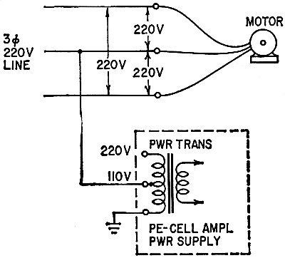
The photocell controller for a factory conveyor refused to work after reinstallation
in a new spot. It was supposed to stop the conveyor motor when a box broke the beam.
A 3-phase 220-volt line supplied power to the motor. The power transformer of the
photocell relay control amplifier, a standard 110-220-volt tapped transformer, was
connected between the center leg of the 220-volt line and ground. The transformer
overheated and resistors burned up. When the tap was moved to 220 volts, the amplifier
still refused to work.
The complete system was taken to the shop. There, it worked perfectly on both
110- and 220-volt supply, yet it refused to work on the machine. What's the matter?
Possible hint for solution:
"Industrial Electrician" employed by local factory was kid who actually didn't
know what three-phase current is. Argued for three days, despite actual demonstrations
on nearby power supply. He got the motor to work by following wire colors, but couldn't
get the photo-cell amplifier to work at all.
- J. Darr
 Output Voltage Output Voltage
What is the output voltage across the bridge? Can you prove it mathematically?
- Cameron McCulloch
 Double Grid Double Grid
All resistors are equal and the total current is 1 ampere. What is the value
of each resistor?
- Kendall Collins
Quizzes from vintage electronics magazines (and many custom RF Cafe-generated
quizzes) such as Popular Electronics, Electronics-World,
QST, Radio-Electronics, and Radio News were published
over the years - some really simple and others not so simple. Robert P. Balin
created most of the quizzes for Popular Electronics. This is a listing
of all I have posted thus far.
- Oscillator
Quiz, November 1962 Popular Electronics
- Vacuum Tube Quiz,
February 1961 Popular Electronics
- Kool-Keeping Kwiz, June
1970 Popular Electronics
- Find the Brightest
Bulb Quiz, April 1960 Popular Electronics
-
Where Do the Scientists Belong? - Feb 19, 1949 Saturday Evening Post
- Quiz
on AC Circuit Theory, December 1970 Popular Electronics
- Magnetic
Phenomena Quiz, February 1962 Popular Electronics
- Electronics
Geography Quiz, April 1970 Popular Electronics
- Electronic
Menu Quiz, August 1963 Popular Electronics
- Electronic
Noise Quiz, August 1962 Popular Electronics
- Electronic
Current Quiz, October 1963 Popular Electronics
- Electronic
Inventors Quiz, November 1963 Popular Electronics
- Resistor Function
Quiz, January 1962 Popular Electronics
- Electronic
Measurement Quiz, January 1963 Popular Electronics
- Electronic
Coupling Quiz, August 1973 Popular Electronics
- Electronics
Analogy Quiz, August 1960 Popular Electronics
- Audio Quiz, April
1955 Popular Electronics
- Electronic Unit
Quiz, May 1962 Popular Electronics
- Capacitor
Circuit Quiz, June 1968 Popular Electronics
- Meter-Reading
Quiz, June 1966 Popular Electronics
- Electronic
Geometry Quiz, Jan 1965 Popular Electronics
- Electronic
Factor Quiz, November 1966 Popular Electronics
- Electronics
Math Quiz, November 1965 Popular Electronics
- Series Circuit
Quiz, May 1966 Popular Electronics
- Electrochemistry
Quiz, Mar 1966 Popular Electronics
- Biz
Quiz: Test Your Sales Ability - April 1947 Radio News
- Electronic
Analogy Quiz, Nov 1961 Popular Electronics
- Diode Quiz, July
1961 Popular Electronics
- Electronic
Curves Quiz, Feb 1963 Popular Electronics
- Electronic
Numbers Quiz, Dec 1962 Popular Electronics
- Energy Conversion
Quiz, April 1963 Popular Electronics
- Coil Function
Quiz, June 1962 Popular Electronics
-
Co-Inventors Quiz - January 1965 Electronics World
-
"-Tron" Teasers Quiz - Oct 1963 Electronics World
- Polarity Quiz
- March 1968 Popular Electronics
-
Television
I.Q. Quiz - Oct 1948 Radio & Television News
- Amplifier Quiz
Part I - Feb 1964 Popular Electronics
- Semiconductor
Quiz - Feb 1967 Popular Electronics
- Unknown
Frequency Quiz - September 1965 Popular Electronics
- Electronics
Metals Quiz - Oct 1964 Popular Electronics
- Electronics
Measurement Quiz - August 1967 Popular Electronics
- Vector-Circuit
Matching Quiz, June 1970 Popular Electronics
- Inductance
Quiz, September 1961 Popular Electronics
- RC Circuit Quiz,
June 1963 Popular Electronics
|
-
LCR Circuits Quiz - November 1969 Electronics World
- Amplifier Quiz Part
2 - March 1964 Popular Electronics
- Amplifier Quiz
Part 1 - February 1964 Popular Electronics
- Three Letter
Quiz - January 1964 Popular Electronics
- Electromagnetic
Function - June 1964 Popular Electronics
- Electronic
Sticklers - February 1959 Popular Electronics
- Bio-Electronic
Quiz - July 1964 Popular Electronics
- Transformer Quiz
- April 1962 Popular Electronics
- Oscilloscope
Quiz - October 1961 Popular Electronics
- Roundword Puzzle
- January 1961 Popular Electronics
- Electronic
Sticklers - April 1959 Popular Electronics
-
What's Your EQ? - August 1966 Radio-Electronics
-
What's Your EQ? - February 1966 Radio-Electronics
-
What's Your EQ? - September 1962 Radio-Electronics
- Electronic Sticklers
- May 1959 Popular Electronics
-
What's Your EQ? - February 1963 Radio-Electronics
-
What's Your EQ? - April 1964 Radio-Electronics
-
What's Your EQ? - October 1966 Radio-Electronics
-
What's Your EQ? - June 1963 Radio-Electronics
-
What's Your EQ? - July 1966 Radio-Electronics
-
What's Your EQ? - December 1966 Radio-Electronics
-
What's Your EQ? - October 1964 Radio-Electronics
-
What's Your EQ? - July 1963 Radio-Electronics
-
What's Your EQ? - March 1966 Radio-Electronics
-
What's Your EQ? - November 1966 Radio-Electronics
-
What's Your EQ? - October 1966 Radio-Electronics
-
What's Your EQ? - May 1966 Radio-Electronics
-
What's Your EQ? - January 1966 Radio-Electronics
-
What's Your EQ - July 1966 Radio-Electronics
-
What's Your EQ? - December 1966 Radio-Electronics
-
What's Your EQ? - October 1964 Radio-Electronics
-
What's Your EQ? - June 1963 Radio-Electronics
-
R-E Puzzler - June 1967 Radio-Electronics
-
What's Your EQ? - January 1963 Radio-Electronics
-
Do You Know the Law? - Nov 1963 Radio-Electronics
-
What's Your EQ? - November 1962 Radio-Electronics
-
What's Your EQ? - September 1966 Radio-Electronics
- Radio
WittiQuiz - October 1938 Radio-Craft
-
What's Your EQ? - November 1964 Radio-Electronics
-
What's Your EQ? - February 1964 Radio-Electronics
-
What's Your EQ? - July 1967 Radio-Electronics
-
What's Your EQ? - December 1962 Radio-Electronics
-
What's Your EQ? - April 1966 Radio-Electronics
-
What's Your EQ? - October 1963 Radio-Electronics
-
What's Your EQ? - July 1964 Radio-Electronics
- Radio
WittiQuiz - November 1937 Radio-Craft
-
What's Your EQ? - May 1967 Radio-Electronics
-
What's Your EQ? - July 1962 Radio-Electronics
-
What's Your EQ? - January 1962 Radio-Electronics
-
What's Your EQ? - February 1962 Radio-Electronics
-
What's Your EQ? - March 1962 Radio-Electronics
-
What's Your EQ? - July 1961 Radio-Electronics
-
What's Your EQ? - August 1961 Radio-Electronics
-
Can You Name These Strange Electronic Effects? - August 1962 Radio-Electronics
-
What's Your EQ? - September 1961 Radio-Electronics
-
What's Your EQ? - September 1962 Radio-Electronics
-
What's Your EQ? - October 1961 Radio-Electronics
- Radio
WittiQuiz - December 1937 Radio-Craft
-
What's Your EQ? - November 1961 Radio-Electronics
-
What's Your EQ? - March 1964 Radio-Electronics
-
What's Your EQ? - April 1962 Radio-Electronics
-
What's Your EQ? - May 1962 Radio-Electronics
-
What's Your EQ? - June 1962 Radio-Electronics
-
What's Your EQ? - April 1967 Radio-Electronics
-
What's Your EQ? - March 1967 Radio-Electronics
-
What's Your EQ? - December 1964 Radio-Electronics
-
What's Your EQ? - January 1967 Radio-Electronics
-
Wanted: 50,000 Engineers - Jan 1953 Popular Mechanics
-
What's Your EQ? - August 1964 Radio-Electronics
- Voltage Quiz
- December 1961 Popular Electronics
-
What is It? - June 1941 Popular Science
- What Do You Know
About Resistors? - April 1974 Popular Electronics
-
What's Your EQ? - September 1963 Radio-Electronics
- Potentiometer Quiz - Sep
1962 Popular Electronics
-
Mathematical Bafflers - March 1965 Mechanix Illustrated
- Op Amp Quiz -
October 1968 Popular Electronics
- Electronic "A"
Quiz - April 1968 Popular Electronics
-
What's Your EQ? - May 1961 Radio-Electronics
-
Popular Science Question Bee - Feb 1939 Popular Science
-
What is It? - A Question Bee in Photographs - June 1941 Popular Science
-
What's Your EQ? - June 1961 Radio-Electronics
-
What's Your EQ? - June 1964 Radio-Electronics
-
What's Your EQ? - May 1964 Radio-Electronics
-
What's Your EQ? - August 1963 Radio-Electronics
-
What's Your EQ? - May 1963 Radio-Electronics
- Bridge
Function Quiz - Sep 1969 Radio-Electronics
-
What's Your EQ? - March 1963 Radio-Electronics
-
What's Your EQ? - February 1967 Radio-Electronics
-
Circuit Quiz - June 1966 Radio-Electronics
-
What's Your EQ? - June 1966 Radio-Electronics
- Electronics
Mathematics Quiz - June 1969 Popular Electronics
- Brightest
Light Quiz - April 1964 Popular Electronics
-
What's Your EQ? - April 1963 Radio-Electronics
- Electronics "B" Quiz
- July 1969 Popular Electronics
- Ohm's Law Quiz
- March 1969 Popular Electronics
-
Antenna Quiz - November 1962 Electronics World
- Color Code Quiz
- November 1967 Popular Electronics
- CapaciQuiz
- August 1961 Popular Electronics
- Transformer
Winding Quiz - Dec 1964 Popular Electronics
-
Audiophile Quiz - November 1957 Radio-electronics
- Capacitor
Function Quiz - Mar 1962 Popular Electronics
- Greek Alphabet
Quiz - December 1963 Popular Electronics
- Circuit
Designer's Name Quiz - July 1968 Popular Electronics
-
Sawtooth Sticklers Quiz - Nov 1960 Radio-Electronics
-
Elementary
Radio Quiz - December 1947 Radio-Craft
- Hi-Fi
Quiz - October 1955 Radio & Television News
- Electronics Physics
Quiz - March 1974 Popular Electronics
- A Baffling Quiz
- January 1968 Popular Electronics
- Electronics IQ
Quiz - May 1967 Popular Electronics
- Plug and Jack
Quiz - Dec 1967 Popular Electronics
- Electronic
Switching Quiz - Oct 1967 Popular Electronics
- Electronic
Angle Quiz - Sep 1967 Popular Electronics
- International
Electronics Quiz - July 1967 Popular Electronics
- FM Radio
Quiz - April 1950 Radio & Television News
- Bridge Circuit
Quiz -Dec 1966 Popular Electronics
- Diode Function
Quiz - August 1965 Popular Electronics
- Diagram Quiz,
August 1966 Popular Electronics
- Quist Quiz - November
1953 QST
- TV Trouble Quiz,
July 1966 Popular Electronics
- Electronics History Quiz,
Dec 1965 Popular Electronics
- Scope-Trace Quiz,
March 1965 Popular Electronics
-
Electronic
Circuit Analogy Quiz, April 1973
-
Test Your Knowledge of Semiconductors, August 1972 Popular Electronics
- Ganged Switching
Quiz, April 1972 Popular Electronics
- Lamp Brightness
Quiz, Jan 1969 Popular Electronics
- Lissajous
Pattern Quiz, Sep 1963 Popular Electronics
- Electronic
Quizoo, October 1962 Popular Electronics
- Electronic
Photo Album Quiz, March 1963 Popular Electronics
- Electronic
Alphabet Quiz, May 1963 Popular Electronics
- Quiz: Resistive?
Inductive? or Capacitive?, October 1960 Popular Electronics
|
Answers
to What's Your Eq?
These are the answers.
Puzzles on page 39.
Power Supply Puzzler
Wrong primary power supply! You can not get "110 volts" or "220 volts", single-phase,
by tapping into a three-phase 220-volt supply line! The voltage read between the
center leg and ground actually comes out something like 165 volts or more, depending
upon how good the ground is! This is due to the waveform of the voltage; the actual
average voltage between any wire and earth ground is far above a single-phase average!
Came out something like 165 or 175 volts, which, of course, burned up resistors
in the photocell amplifier. Solution: Run a single-phase 110-volt line from a nearby
lighting circuit to the amplifier, which then worked perfectly.
 Output Voltage Output Voltage
The ratio of output voltage (as measured with a vtvm) to input voltage is always
1/2 - for any frequency including dc, any value of C or any value of R! The only
requirement is that the two resistors marked r be equal.
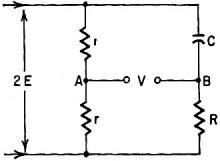
Proof? Here goes. (See the diagram.) For convenience, let's call the input voltage
2E (we can call it any-thing we like, after all). Since r = r, the voltage at A
(VA) must be 1/2(2E), or just E. By the same voltage-divider reasoning,
the voltage at B (VB) will be
VB = 2E(R/(R - jXC),
where jXC is C's reactance. Now we know VA and VB
(at least in symbols). The output voltage V must be the difference between them:
V = VA - VB. Substituting our expressions for VA
and VB, we get
But the absolute value (magnitude) of the expression in parentheses is just 1
(unity), hence V = E, or exactly half the input. Note that the proof contains no
f's or omegas - the voltage does not depend on frequency - and also that the R's
and X's drop out. Thus the solution holds, as we said, for any value of f, C or
R.
Double Grid
This is simply the old cube circuit, presented in an unconventional way. Each
resistor is 6 ohms. An equivalent circuit is shown for convenience in analyzing
the cube circuit. The voltages at a, b and c are identical, as are those at d, e
and f. Therefore, they can be shown connected together for purposes of calculation.
Then, if the effective resistance of the circuit is 5 ohms (5 volts/1 amp) the value
of anyone resistor in the circuit can be found:
R = I network resistor
5 ohms = 1/3 R + 1/6 R + 1/3 R
5 ohms = 5/6 R
R = 6 ohms.
|