|
August 1932 Radio-Craft
 [Table
of Contents] [Table
of Contents]
Wax nostalgic about and learn from the history of early electronics.
See articles from Radio-Craft,
published 1929 - 1953. All copyrights are hereby acknowledged.
|
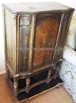 For several years I have been scanning
and posting Radio Service Data Sheets like this one featuring the RCA Victor Model
R-78 B1-Acoustic 12-Tube Superheterodyne floor console radio in graphical format,
and run OCR on them to separate the textual content and make it searchable. There
are still many people who restore and service these vintage radios, and often it
can be difficult or impossible to find schematics and/or tuning information. I will
keep a running list of all data sheets to facilitate a search. The RCA Victor Model
R-78 B1-Acoustic 12-Tube photo was found on the
RadioMuseum.org
website. For several years I have been scanning
and posting Radio Service Data Sheets like this one featuring the RCA Victor Model
R-78 B1-Acoustic 12-Tube Superheterodyne floor console radio in graphical format,
and run OCR on them to separate the textual content and make it searchable. There
are still many people who restore and service these vintage radios, and often it
can be difficult or impossible to find schematics and/or tuning information. I will
keep a running list of all data sheets to facilitate a search. The RCA Victor Model
R-78 B1-Acoustic 12-Tube photo was found on the
RadioMuseum.org
website.
RCA Victor Model R-78 B1-Acoustic 12-Tube Superheterodyne Radio Service Data
Sheet
 (Also, General Electric "Convention" Model
J-125 Chassis.) (Also, General Electric "Convention" Model
J-125 Chassis.)
This is the first commercial receiver to incorporate the new "super-phonic" line
of tubes which have recently made their appearance on the market. The tubes of this
series incorporated in the R-78 (and J-125) chassis are the 58 R.F. pentode, 56
general-purpose, 46 Class Band 82 mercury-vapor rectifier. (The type 58 tubes are
of 6-prong-base design.)
A feature of the receiver is the tone control, which is designed to maintain
even reproduction of the low and high frequencies, regardless of the volume setting.
Thus, bass reproduction at low volumes is not attenuated as when, non-compensating
circuits are used.
The resistance and capacity values of the respective units are indicated by figures
within parentheses.
The following operating voltage and current readings are for a 120-volt line,
the volume control set at "minimum," and no signal being received.
Filament potential, all tubes, 2.5 volts. Plate potential (to cathode or filament),
V1, V2, V4, V6, V7, V10, 210 volts; V3, 70 volts; V5, 200 volts; V8, V9, 400 volts;
V11, zero. Plate current, V1, VI0, 3 ma.; V2, 1.5 ma.; V3, V6, V7, 5 ma.; V4, 2.5
ma.; V5, 1.0 ma.; V8, V9, 6 ma.; V11, zero. Control-grid potential (to cathode or
filament), V1, V2, V3, V4, V8, V9, VI0, V11, zero; V5, 12 volts; V6, V7, 8 volts.
Screen-grid (to cathode or filament), V1, 100 volts; V2, V4, V10, 95 volts. Cathode
(to heater) potential, V1, V3, V10, 7 volts; V2, 10 volts; V4, 8 volts; V5, 12 volts;
V6, V7, 11 volts; V11, 15 volts.
The input signal potential for the I.F. amplifier is applied also to the A.V.C.
amplifier tube due to the grids of both being coupled together by means of C32.
The output of the I.F. amplifier V4 is applied to second-detector V5 through a sharply-tuned
transformer I.F.T.2; however, the output of A.V.C. amplifier V10 is coupled to A.V.C.
tube V11 through a broadly tuned unit.
Although too much selectivity ahead of V11 is undesirable, since it introduces
excessive distortion and overload as a station signal is tuned in, still, a certain
amount is essential; otherwise, the A.V.C. will be caused to function by a local
station when it is desired to tune in a weaker station on an adjacent channel.
The voltage developed across resistors R4, R21, R222, furnish control-grid bias
for V1 ; the drop across R4, R22, is the control-grid bias for V2; and the drop
across R4, control-grid bias for V4.
As the drop in these resistors is due to the signal potential applied to the
A.V.C. tube and this voltage is in turn dependent upon the bias of the R.F. first
detector, and I.F. amplifier, an automatic action is obtained; greater voltage is
applied to the I.F. and first-detector than to the I.F. to prevent overloading of
these tubes due to a strong, undesired adjacent carrier.
The undistorted power output of the R-78 is rated at 10 to 20 watts, depending
upon the percentage of modulation of the incoming signal; consequently, to compensate
for variations in sound intensity over the audio frequency band as the output is
varied within these limits the volume control circuit is arranged to produce substantially
flat response between the range of 35 and 5,000 cycles.
The trap circuit A.F.C.1, C11 tunes to approximately the middle of the A.F. response
range and as the volume is reduced to one point, it causes greater attenuation of
the middle register than at either end. From this point to the minimum position
the volume control acts as a potentiometer across the trap circuit and reduces the
volume without changing the frequency response to any greater degree.
This completes the description of the first half of the volume control; the second,
which functions only over the last 20 degrees of the angular movement of the volume
control, is resistor R1 connected between the R.F. and first-detector cathodes and
varies the overall sensitivity.
Push-pull voltage amplifier V6-V7 is the driver stage for push-push amplifier
V8-V9.
Cabinet resonance bas been nullified by means of two side chambers; the baffle
area is large.
To prevent excessive hum and noise, it is essential that a good ground be connected
to the yellow lead of the chassis; considerable hum also may be caused by insufficient
twist in the volume control leads, due to pickup by A.F.C. 1.
Schematic circuit of the RCA Victor Model R-78 receiver. The same circuit is
used in the G.E. "Convention" Model J-125 set. All the tubes are of the new "superphonic"
series. The power consumption of the set averages 110 watts; and varies between
70 and 130 watts, depending upon the degree of output volume. The undistorted power
output may reach 20 watts during heavy passages in the program of a strong station.
In localities remote from strong stations it may be desirable to increase the
A.V.C. action to obtain better than 100 mv, sensitivity. This is accomplished by
shorting out R1, as indicated by the dotted line, "short."
To realign the chassis, an output meter will be necessary. (This mar be a current-squared
galvanometer connected to the secondary of T3 in place of the reproducer voice coil;
an 0-5 ma. meter in the plate supply lead to V2; or a low-range A.C. voltmeter across
the reproducer voice coil.)
A "dummy" 56-type tube having an open heater circuit is required to replace V11;
make certain that the dial pointer reads exactly at the short line on the scale
when the gang condenser plates are fully meshed. Then, align the circuits at 1,400
kc., with the volume control in the "maximum" position.
Follow this with the alignment procedure at 600 kc., then repeat the procedure
at 1,400 kc. Condenser C4A, the 600 kc. trimmer, is reached through a hole in the
top of the chassis, and about half-way along a line drawn from the tuning dial to
the socket of the first-detector.
To adjust the I.F. circuits, set the service oscillator at 175 kc., replace the
regular type 56 tube with the dummy 56, as previously described, couple the oscillator
to the control-grid of the first-detector, and set the volume control at "maximum";
adjust first I.F.T.2, then I.F.T.1. Repeat the procedure. Looking at the rear skirt
of the chassis, and reading from left to right. the trimmers of the I.F. transformers
are arranged in the following order: C8, C7, C6, C5. Terminal panel P1 is below
these adjustments. At the left of P1 is the "fidelity'" switch, SW.1.
It is a good plan after making the I.F. realignment adjustments to repeat the
oscillator and R.F. adjustments.
Following is the color code of the power transformer: 1, black, red tracer; 2
black-red; 3, red; 4, 5, yellow; 6, 8, brown; 7, brown-black; 9, 11, blue; 10, blue-yellow;
12, 14, green; 13, green-yellow.
Posted September 27, 2022
(updated from original post
on 7/27/2015)
Radio Service Data Sheets
These schematics, tuning instructions, and other data are reproduced from my
collection of vintage radio and electronics magazines. As back in the era, similar
schematic and service info was available for purchase from sources such as
SAMS Photofacts, but these printings
were a no-cost bonus for readers. There are 255 Radio Service Data Sheets as of
April 30, 2025.
- Westinghouse
Models H-164, H-166, H-167
- Belmont Model
4B115
- General Electric
Models 354, 355
- AMRAD
Model 81 "Bel Canto"
-
GE Model 250 Radio Service Data Sheet
- Hoffman
Model A300
- Emerson
Model 505
- Olympic
Models 6-501, 6-502, 6-503
- Radiola
Models 61-5, 61-10
- Farnsworth
Models ET-060, ET-061, ET-063
- General
Electric Model 321
-
Garod Model 6AU-1
- Truetone
Model D4620
- Westinghouse
Model H-148
- Wards Models
54BR-1501A, 1502A
- Majestic
Models 8S452, 8S473
- RCA Models
Q22A, Q32
- Zenith Model
5G003ZZ
- Mantola Models
92503 and 92504
- Emerson Model
508 Series 8-7434351 and Up
- Belmont Model
A-5D118
- Wards Model
74BR-2707A
- Crosley Model
56TP-L
- Meck FM Converter
- Admiral Model
7C60 Chassis 6B1
- Zenith Model
8G005
- 336
Belmont Radio Model 6D111, Series A
-
333 General Electric Models 100, 101, 103 and 105
- RCA Victor
Models 54B1, 54B-N, 54B2, 54B3 Radio Data Sheet 335
-
National Union "Presentation" Radio Model G-619
-
Zenith Radio Models 8H032, 8H033, 8H050, 8H052, 8H061
-
General Electric Farm Radio Model 280
-
Admiral Model 6RT44-7B1
-
Montgomery Ward Airline Model 04BR-1105A Radio
- Belmont
Model 678 Auto-Radio Set
- Sentinel
Model 217-P Portable Radio Set Radio
- Remler
Model No. 36 Dual-Wave Auto-Radio
-
Stromberg-Carlson No. 82 All-Wave Receiver
-
Majestic A.V.C. Model 290 Chassis
- FADA 9 Tube
Model 190 "Metal" All-Wave
- RCA Victor
Models 9T and K2 9-Tube, 5- to 566-Meter
-
Motorola "Golden Voice" Model
-
RCA Victor Model H-6
-
Simplex Model TA
-
Automatic "Magic Eye" Model A1
- Silvertone
Models 4488 and 4588 (Chassis No.101412) and 4488A and 4588A (Chassis No. 101412A)
- RCA Victor
Model M109 "De Luxe" 7-Tube Auto-Radio Receiver
- Crosley Model
6625 6-Tube 3-Band Receiver
- International
Model 77 Series 7-Tube Dual-Band Receiver
- Belmont
Model 6D121
-
General Electric Models 60, 62
- Admiral
Model 7C64
-
Radiola "28" Super and "104" Power Speaker
- Sonora
Model TW-49
-
Stromberg-Carlson Models 1020, 1120, Series 10
- Air King
Model 4604D
- Sparton Models
526, 526X, 526PS
- Truetone
Model D2624
- Admiral
Models 6EI, 6EIN
- Detrola Models
571A, 571B
-
General Electric Model 250
- Howard Model
920
- Colonial
Model 652 5-Tube Broadcast-Short-Wave
-
Fairbanks-Morse
9-Tube All-Wave Model 91
-
International Model 500 5-Tube Dual-Range Battery
- Emerson Model
678 "Auto-Dynamic" 5 Tube
-
Stromberg-Carlson
Nos. 230 and 231 Series
- Atwater
Kent Model 649 All-Wave
-
Howard Model G-26, and "Airplane 4" Model AA25
-
Montgomery Ward "Airline" Series 7GM 7-Tube High-Fidelity Receiver
- RCA
Victor Model T5-2 5-Tube, 2-Band A.C. Superheterodyne Receiver
-
Majestic
"Models 50," "51" and "52"
-
Bremer-Tully Model 7-70 and 7-71
-
General
Electric Model M-49 4-Tube Radio-Phonograph Dual-Wave Superheterodyne
- RCA-Victor
Radiola "Superette" Model R7 Superheterodyne
- Crosley Model AC-7
and AC-7C
-
Westinghouse
"Columnaire" Models WR-8 and WR-8-R (Remote Control)
-
Characteristics
of Metal Tubes - and Other "Octal" (8-Prong) Base Types
- Kolster K20,
K22, K25, K27 and K37 Six-Tube Receivers
-
Stromberg-Carlson
Nos. 62 and 63, 8-Tube High-Fidelity Chassis
- RCA Model
103, 4-Tube A.C. Compact Dual-Wave
- FADA "Special"
Model 265-A and FADA "7" Model 475-A
-
General Electric Model C-62 6-Tube Battery
- Emerson
5A Automotive
- Zenith
666 Automotive
- Motorola
100 Automotive
-
Crosley
Roamio 4-A-1 Automotive
-
American-Bosch
524A Automotive
- Crosley
Model 1316 (in Model 167 Console)
- RCA Victor
"High-Fidelity Electrola," Model R-99
- AMRAD
Model 81 ("Bel Canto" Series) Receiver
-
Fada 103 Fadalette, Stewart-Warner Series 108, DeWald 54 Dynette Sets
- RCA
Victor R-27 and Philco 53 Ultra-Midget A.C.-D.C. Radio Receivers
-
Majestic Models Fairfax and Sheffield 8-Tube
- Stromberg-Carlson
No. 29, 9-Tube Superhet
-
International Kadette Model 400 4-Tube Battery-Operated Superhet
- RCA Victor
Model 5M 5-Tube Auto Superhet
-
Majestic Model 11 Short-Wave Converter
-
Silver-Marshall
Model 727-DC Battery-Operated Superheterodyne
- RCA
Victor Model VHR-307 Home Recording - Phono-Radio Combination
-
Delco 32-Volt Radio Receiver Chassis Models RA-3, RB-3 and RC-3
- Majestic
Chassis Models 380 A.C. T.R.F., and 400 A.C.-D.C. Superheterodyne
- General
Motors S1A, S1B
- Admiral
Model 7C63, Chassis 7C1
- Westinghouse
Model H-133
- Arvin
Models 150TC, 151TC
- Kadette Model
90 Duplex
-
RCA-Victor "Magic Brain" Model 281
- Grunow
11A Chassis 11-Tube All-Wave Superheterodyne
-
Sears, Roebuck & Co., Silvertone "Rocket" Models 6110 and 6111
-
General Electric Model GD-52
-
Zenith Models 6D302, 6D311, 6D326, 6D336, 6D360
-
Allied Radio, Knight Model E10913
- Arvin Model
140P
- Emerson
Models 501, 502, 504
- Crosley
Model 56TD-W
- Hoffman
Model A500
-
Stewart-Warner
Model 9003-B
-
Zenith Models 6D014, 6D029
- Coronet
Model C-2
- Sparton
Models 7-46, 7-46PA, 8-46, 8-46PA
-
Stewart-Warner Models 9001-C, D, E, F
-
Zenith Models 5D011-5D027
- Bendix Models
636A, C, D
- ECA Model 108
-
International Model 66 and 666, 6-Tube Superhet
-
Ford-Philco
Radio, Model FT9, 6-Tube Auto-Radio Receiver
- Howard
Explorer Model W Deluxe 19 Tube All-Wave Superhet
- RCA Victor
Portable Table Electrola Model R-95
- Atwater
Kent Model 305Z 5-Tube 32 V. D.C. Superhet
- Kadette
Jewel Model 40 Chassis 3-Tube Ultra-Midget Receivers
-
General Electric Model N-60 6-Tube Auto Superheterodyne
-
Sparton Model 40 6-Tube T.R.F. Automotive Receiver
-
Clarion "Replacement" Chassis, Model AC-160 A.V.C. Superheterodyne
- Emerson Models
20A and 25A
- General
Electric K-40A
- Pilot Model
B-2
- RCA-Victor
Radiola Model M-30 Automotive Radio
- Motovox
Models 10A All-Electric and 10E Battery-Operated "Moto-Tetradynes"
-
Kennedy Superheterodyne Short-Wave Converter
- RCA
Victor Model R-78 B1-Acoustic 12-Tube
- Philco
Model 15 Series, 11-Tube Superheterodyne Chassis
-
Zenith Challenger Model 740
-
Sparton
Selectronne Receivers Models 1068 and 1068X
- Fada Model
155 Super Fadalette A.C.-D.C. Set
-
Clarion De Luxe Models AC-280 and 25-280
-
Crosley Model A-157 (River Roamio) Auto Radio
- Philco Model
'37-116 Codes 121 (Shadometer) and 122 (Dial Tuning)
-
Arvin Model 28
-
Philco Model 818
-
Fada Model 266 Motoset
-
Bosch Models 736, 737, 738
- RCA-Victor
Model 15U, Radio-Phonograph
- Sparton
Models 566 ("Bluebird" Mirror), A.C.-D.C. 5-Tube 2-Band Midget Superhet
- Atwater
Kent Model 776 6-Tube Auto Radio
- Stromberg-Carlson
No. 61 4-Band 7-Tube A.C.-D.C. Receiver
- Arvin Model
182TFM
- Crosley
Model 58TK
- Westinghouse
Model H-165
-
General Electric Models G-105 and G-106
- Silvertone
"F," "FF," "G," "H," and "J"
-
Stewart-Warner Model 03-5A1 to 03-5A9 (Chassis 03-5A) Senior Varsity Radio
- Radiola Models
61-6, 61-7
-
Westinghouse
Models H-104, H-105, H-107, H-108
- Farnsworth
Models EC-260, EK-262, EK-263, EK-264, EK-265
-
United
Models 980744, 980745
-
Stewart-Warner (R-127 Chassis) Models 1271 to 1279 All-Wave
- ERLA Model
4500 Dual-Wave T.R.F. 4-Tube A.C. Receiver
- Clarion No. TC-31
5-Tube A.C.-D.C. Superhet.
- Detrola Model
105C 5-Tube Dual-Band A.C.-D.C.
- Zenith
6-Tube All-Wave Chassis No. 5634
- RCA Victor
Model 261, 555 to 107 Meter
- Philco
Model 38-116; Code 125
-
Stewart-Warner "Ferrodyne" Chassis Model R-136
-
American-Bosch
Model 43OT 5-Tube 3-Band Superheterodyne
- RCA
Victor Model C9-4 9-Tube 3-Band Superheterodyne
- Kennedy "Model
826B" Combination Receiver
- Steinite
50-A and 102-A
- Pilot Model
63 All-Wave 6-Tube Superheterodyne
- Stromberg-Carlson
No. 69 4-Tube All-Wave Superhet. Selector (Converter)
- RCA
Victor Model 102 4-Tube A.C.-D.C. T.R.F. Receiver
- Bosch Models 60
and 61
-
Atwater Kent Models 30, 33, 35, 48 and 49
- Crosley Model
120 Senior Superheterodyne (Pliodynatron) Chassis
-
Columbia Screen-Grid 8 Receiver
-
General Electric Models A82 and A87, 8-Metal-Tube All-Wave A.C. Superhet.
- Colonial
31 and 32 D.C.
- Zenith 5-Tube
Triple-Wave Chassis nos. 5508 and 5509
- Remler Model
46 ("Scottie")
- General
Electric FA-60 and FA-61
-
Stewart-Warner
Series 900
-
Howard
Model B-5 (715), Series 1 and 2 (Sheaffer Radio-Clock-Pen Desk Set)
-
Ford-Philco Car-Radio Models F-1440 and F-1442
-
Brunswick Model 31 Combination Radio and Panatrope
- Emerson Models
38, 42 and 49, 6-Tube Dual-Wave (Chassis U6)
-
General Motors Chevrolet No. 601574 Automotive
-
RCA Victor M-104 (and M-108) Automotive
- Arvin-Ford
17-A Automotive
-
Westinghouse Model WR 207 & WR 208 5-Tube Dual-Band Superheterodyne
- Radiolas
"Super VIII" (AR-810, "Semi-Portable" (AR-812), 24 and 26
- Howard Model
45 A. V. C.
- Majestic
Model 25
-
Galvin Motorola Model 61
-
Arvin Model 6
- Admiral
Models 7T06, 7T12
- Garod Model 5A1
- Hoffman Model A301
-
Knight Model E10716 Battery Portable
- Arvin Models 555,
555A, 552N, 552AN
- Grantline Models
605, 606
- Truetone Model
D2616
- Belmont Model
5D128
- Arvin Models 444,
444A
-
International Kadette Model 1019
-
Stewart-Warner Models 97-561 to 97-569
- General
Electric Model 280
- Zenith Models 5R080,
5R086
- Truetone Models
D1747, D1748
-
Crosley Roamio Automotive T.R.F. Models 90, 91, 92
-
Crosley Roamio Automotive Superheterodyne Models 95, 96
-
Wells-Gardner Series 062
-
Emerson
Model AZ-196
- Belmont Model
5P19
- Crosley Fortyfive
- Crosley Model
56FC
-
Emerson
Models 507, 509, 518, 522, 535
- Garod Model 6AU-1
- General
Electric Models 219, 202, 221
-
Crosley "Chairside" Model 567
-
Belmont Model 408 Battery "Farm"
- Wards Model
74BR-1055A
- Farnsworth
Models EK-081, EK-082, EK-083, EK-681
- Philco
Model 200-X Radio
-
Admiral "Aeroscope" Models 161-5L, 162-5L and 163-5L
- Philco
Model 59, 4-Tube A.C. Midget Superheterodyne
- Zenith
Farm Model 6V 27, 6-Tube Superhet
- Ward 10-Tube
All-Wave High-Fidelity Superhet, Series ODM
-
Philco-Packard
Deluxe
-
Canadian
Westinghouse Model 175
- Crosley Model
1155
- Philco Models
39 and 39A
-
Arvin Model 35 8-Tube Car-Radio
- Hetro
Air-Ace Series M
- Westinghouse
Models H-161, H-168, H-168A
- Garod Model 5A4
- Arvin Models 152T,
153T
- Belmont Model 5240
- Mantola Models 92505,
92506
- General Electric
Models 102, 102W, 107, 107W, 114, 114W, 115, 115W
- Crosley Model
555 (A.F.M.)
- Crosley Model
515 (Fiver)
- Crosley Model
425 (Travo)
-
Firestone-Stewart-Warner Model R1332
- Fairbanks-Morse
Model 81 "Farm" Set
- Clarion Model
423, 470, 471, 472, 480
-
International Radio Corp. Model 90
- Belmont Model
578 Series A
|


