Module 16 - Introduction to Test Equipment
Pages i,
1-1,
1-11,
1-21,
2-1,
2-11,
2-21,
3-1,
3-11,
3-21,
3-31,
4-1,
4-11,
4-21,
5-1,
5-11,
5-21,
5-31,
6-1,
6-11,
6-21,
6-31,
6-41, Index
portion of it)
directly to the meter terminals. The resulting excessive current burns up the meter coil and renders the meter useless until repaired. Q-11. In what manner are current-measuring instruments connected to a circuit?
If you do not know the approximate value of current in the circuit, you should take a reading at the highest
range of the ammeter; then you should switch progressively to lower ranges until a suitable reading is obtained.
Most ammeter scales indicate the current being measured in increasing values from left to right. If you connect
the meter without observing proper polarity, the pointer may be deflected backwards (from right to left). This
action often damages the meter movement. You should ensure that the ammeter is always connected so that the
current will flow into the negative terminal and out the positive terminal. Figure 3-6 shows various circuit
arrangements and the proper ammeter connection methods to measure current in various portions of the circuit.
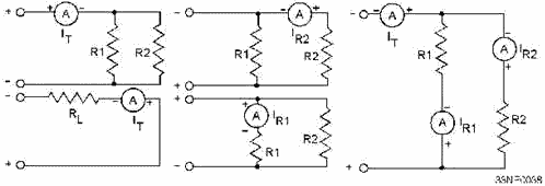
Figure 3-6. - Proper ammeter connection. Q-12. An ammeter should always be connected so that current will flow into what terminal and out of
what terminal? Ammeter Sensitivity Ammeter sensitivity is determined by the
amount of current required by the meter coil to produce full-scale deflection of the pointer. The smaller the
amount of current required to produce this deflection, the greater the sensitivity of the meter. a meter movement
that requires only 100 microamperes for full- scale deflection has a greater sensitivity than a meter movement
that requires 1 milliampere for the same deflection. Q-13. (True or False) The larger the current
required to produce full-scale deflection of the meter coil, the better the sensitivity of the meter.
Good sensitivity is especially important in ammeters to be used in circuits in which small currents flow. As the
meter is connected in series with the load, the current flows through the meter. If the internal resistance of the
meter is a large portion of the load resistance, an effect known as METER-LoadING will occur. Meter-loading is the
condition that exists when the insertion of a meter into a circuit changes the operation of that circuit. This
condition is not desirable. The purpose of inserting a meter into a circuit is to allow the measurement of circuit
current in the normal operating condition. If the meter changes the
3-11
circuit operation and changes the amount of current flow, the reading you obtain will be in error. An
example of this is shown in figure 3-7.
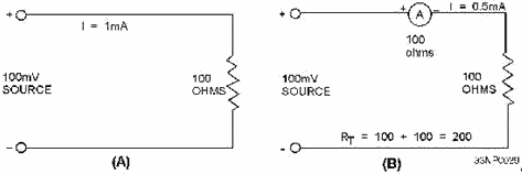
Figure 3-7. - Ammeter loading effect. Q-14. What condition exists when the insertion of a meter into a circuit changes the operation of the
circuit? In view a of figure 3-7, the circuit to be tested has an applied voltage of 100 millivolts and a
resistance of 100 ohms. The current normally flowing in this circuit is 1 milliampere. In view B, an ammeter that
requires 1 milliampere for full-scale deflection and that has an internal resistance of 100 ohms has been
inserted. Since 1 milliampere of current flow is shown in view A, you might naturally assume that with the meter
inserted into the circuit, a full-scale deflection will occur. You might also assume that the 1 milliampere of
circuit current will be measured. However, neither of these assumptions is correct. With the ammeter inserted into
the circuit, as shown in view B, the total resistance of the circuit is 200 ohms. With an applied voltage of 100
millivolts, applying Ohm's law shows the actual current (Icircuit) to be 0.5 milliampere.
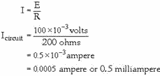
Since the meter reads 0.5 milliampere instead of the normal value of current, the meter reveals that a
definite loading effect has taken place. In cases such as this, the use of ammeters, which have a lower internal
resistance and a better current sensitivity, is desirable. DC VOLTMETER
Up to this point, we have been discussing the 100-microampere D'Arsonval movement and its use as an ammeter.
However, it can also be used to measure voltage if a MULTIPLIER (high resistance) is placed in series with the
moving coil of the meter. For low-voltage instruments, this resistance is physically mounted inside the meter case
with the D'Arsonval movement. The series resistance is constructed of a wire-wound resistance that has a low
temperature coefficient wound on either a spool or
3-12
card frame. For high-voltage ranges, the series resistance can be connected externally. a simplified
diagram of a voltmeter is shown in figure 3-8.
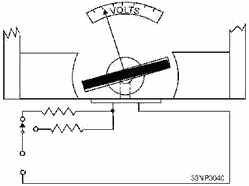
Figure 3-8. - Internal construction and circuit of a simplified voltmeter. Q-15. What modification is made to the D'Arsonval meter movement to enable the meter to measure
voltage? Keep in mind that the D'Arsonval meter movement uses current flow to produce a magnetic field that is
proportional to the current. The meter movement is, therefore, an indicator of current flow rather than voltage.
The addition of the series resistance is what allows the meter to be calibrated in terms of voltage; that is, the
meter movement of a voltmeter operates because of the current flow through the meter, but the scale is marked in
volts. For example, the meter movement shown in figure 3-9 has an internal resistance of 100 ohms, requires 100
microamperes for full-scale deflection, and has a voltage drop of 10 millivolts when full-scale deflection is
reached. If you were to place this meter directly across a 10-volt source, an excessive current (in milliamperes)
would flow. The meter would be destroyed because of the excessive current flowing through the meter movement. This
can be seen in the following Ohm's law application:

Figure 3-9. - use of multiplier resistors with D'Arsonval meter movement. Using this equation, you can see that a current through the meter of 100 milliamperes is excessive and
will cause damage.
3-13

Since the normal voltage drop for the meter is 10 millivolts at full-scale deflection, some means must
be supplied to drop the extra 9.99 volts without applying it directly to the meter. This is done by the addition
of a multiplier resistor, as shown in figure 3-9. Extending Voltmeter Ranges
The value of series resistance is determined by the current required for full-scale deflection and by the range of
the voltages to be measured. Since the current through the meter circuit is directly proportional to the applied
voltage, the meter scale can be calibrated directly in volts for a fixed value of series resistance. For example,
let's assume that the basic meter is to be made into a voltmeter with a full- scale deflection of 1 volt. The coil
resistance of the basic meter is 100 ohms, and 100 microamperes of current causes full-scale deflection. The
resistance (Rmeter) required to limit the total current in the circuit to 100 microamperes can be found
as follows:

Because the meter coil already measures 100 ohms, the series resistance required is equal to 10 kilohms
minus 100 ohms, or 9.9 kilohms. Q-16. What factors determine the value of the multiplier resistor?
Multirange voltmeters use one meter movement. The required resistances are connected in series with the meter by a
switching arrangement. a schematic diagram of a multirange voltmeter with three ranges is shown in figure 3-10.
The total meter resistance (Rmeter) for each of the three ranges, beginning with the 1-volt range, is
figured by the application of Ohm's law, as follows:
3-14
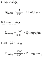
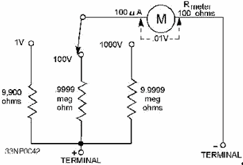
Figure 3-10. - Multirange voltmeter. The actual value of the multiplying series resistor (Rseries) for each of these circuits is
100 ohms less than the total resistance. This allows for the resistance of the meter coil (Rcoil).
Voltmeter Circuit Connections When voltmeters are used, a primary rule of safety is that
such voltage-measuring instruments must always be connected in parallel with (across) a circuit.
If you are unsure of the level of the voltage to be measured, take a reading at the highest range of the voltmeter
and progressively (step by step) lower the range until a suitable reading is obtained. In many cases, the
voltmeter you will be using will not be a
3-15
center-zero- (0 reading is in the center) indicating instrument. Observing the correct polarity is
important when connecting the instrument to the circuit. Voltmeter polarity is the same as for the dc ammeter;
that is, current flows from negative to positive. Q-17. In what manner are voltage-measuring instruments
connected to the circuit to be measured? Influence of a Voltmeter in a Circuit
The purpose of a voltmeter is to indicate the potential difference between two points in a circuit. When a
voltmeter is connected across a circuit, it shunts the circuit. If the voltmeter has a low resistance, it will
draw a substantial amount of current. This action lowers the effective resistance of the circuit and changes the
voltage reading. When you are making voltage measurements in high-resistance circuits, use a High-Resistance
VOLTMETER to prevent the shunting action of the voltmeter. The effect is less noticeable in low-resistance
circuits because the shunting effect is less. The problem of voltmeter shunting (sometimes called circuit loading)
is illustrated in figure 3-11.
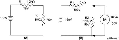
Figure 3-11. - Shunting action caused by a voltmeter. Q-18. When making voltage measurements in a high-resistance circuit, you should always use a voltmeter
with what relative value of resistance? In view a of figure 3-11, a source of 150 volts is applied to a
series circuit consisting of two 10- kilohm resistors. View a shows the voltage drop across each resistor to be 75
volts. In the 150-volt range, the voltmeter to be used has a total internal resistance of 10 kilohms. View B shows
the voltmeter connected across the circuit. The parallel combination of R2 and the meter now present a total
resistance of 5 kilohms. Because of the addition of the voltmeter, the voltage drops change to 100 volts across R1
and 50 volts across R2. Notice that this is not the normal voltage drop across R2. Actual circuit conditions have
been altered because of the voltmeter. Voltmeter Sensitivity The sensitivity of a
voltmeter is given in ohms per volt. It is determined by dividing the sum of the resistance of the meter (Rmeter),
plus the series resistance (Rseries), by the full-scale reading in volts. In equation form, sensitivity
is expressed as follows:

This is the same as saying the sensitivity is equal to the reciprocal of the full-scale deflection
current. In equation form, this is expressed as follows:
3-16
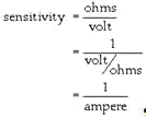
Therefore, the sensitivity of a 100-microampere movement is the reciprocal of 0.0001 ampere, or
10,000 ohms per volt.

Q-19. What term is used to express the sensitivity of a voltmeter?
METERS useD for MEASURING Resistance The two instruments you will use most often to check
continuity, or to measure the resistance of a circuit or circuit component, are the OHMMETER and the MEGGER
(MEGOHMMETER). The ohmmeter is widely used to measure resistance and to check the continuity of electrical
circuits and devices. Its range usually extends to only a few megohms. The megger is widely used for measuring
insulation resistance, such as that between a wire and the outer surface of its insulation, and the insulation
resistance of cables and insulators. The range of a megger can be extended to more than 1,000 megohms.
Q-20. What instrument is used for measuring the insulation resistance of cables? The Ohmmeter
A simple ohmmeter circuit is shown in figure 3-12. The ohmmeter consists of the dc milliammeter, discussed
earlier in this chapter, and the added features shown below:
3-17
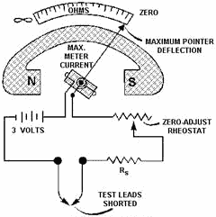
Figure 3-12. - Simple ohmmeter circuit.
· a source of dc potential; and
· One or more resistors (one of which is variable). Q-21. What added features enable
a dc milliammeter to function as an ohmmeter? The deflection of the pointer of an ohmmeter is controlled
by the amount of battery current passing through the moving coil. Before you can measure the resistance of an
unknown resistor or electrical circuit, you must calibrate the ohmmeter to be used. If the value of resistance to
be measured can be estimated within reasonable limits, select a range on the ohmmeter that will give approximately
half-scale deflection when the resistance is inserted between the probes. If you cannot estimate the resistance to
be measured, then set the range switch on the highest scale. Whatever range you select, the meter must be
calibrated to read zero before the unknown resistance is measured. To calibrate the meter, you first short
the test leads together, as shown in figure 3-12. With the test leads shorted, a complete series circuit exists.
The complete series circuit consists of the 3-volt source, the resistance of the meter coil (Rmeter),
the resistance of the zero-adjust rheostat, and the series multiplying resistor (Rseries). The shorted
test leads cause current to flow and the meter pointer to deflect. Notice that the zero point on the
ohmmeter scale (as opposed to the zero points for voltage and current) is located at the extreme right side of the
scale. With the test leads shorted, the zero-adjust potentiometer is set so that the pointer rests on the zero
mark. Therefore, a full-scale deflection indicates zero resistance between the leads. Q-22. a
full-scale deflection on an ohmmeter scale indicates what resistance between the leads? If you change the
range on the meter, you must "zero" (calibrate) the meter again to obtain an accurate reading. When you separate
the test leads, the pointer of the meter will return to the left side of the scale. This action, as explained
earlier, is caused by the restoring force of the spring tension acting on the movable coil assembly. The reading
at the left side of the scale indicates an infinite resistance.
3-18
After you have adjusted the ohmmeter for zero reading, it is ready to be connected to a circuit to
measure resistance. a typical circuit and ohmmeter arrangement is shown in figure 3-13. You must ensure that the
power switch of the circuit to be measured is in the de-energized (ofF) position. This prevents the source voltage
of the circuit from being applied to the meter, a condition that could cause severe damage to the meter movement.
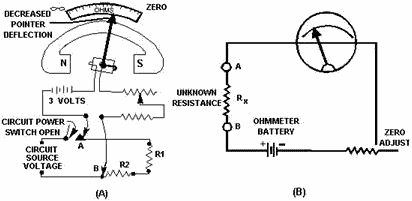
Figure 3-13. - Measuring circuit resistance with an ohmmeter. Remember that the ohmmeter is an open circuit when the test leads are separated. To take a resistance
reading with a meter, you must provide a path for current flow produced by the meter's battery. In view a of
figure 3-13, the meter is connected at points a and B to produce this path. Connecting these test leads places
resistors R1 and R2 in series with the resistance of the meter coil, the zero-adjust potentiometer, and the series
multiplying resistor. Since you previously calibrated the meter, the amount of coil movement now depends only on
the resistances of R1 and R2. The addition of R1 and R2 into the meter circuit raises the total series
resistance and decreases the current. This decreases the amount of pointer deflection. The pointer comes to rest
at a scale reading that indicates the combined resistance of R1 and R2. If you were to replace either R1 or R2, or
both, with a resistor having a larger ohmic value, the current flow in the moving coil of the meter would be
decreased even more. This would further decrease the pointer deflection, and the scale indication would read a
still higher circuit resistance. View B is a simplified version of the circuitry in view A. From our
ohmmeter discussion, two facts should be apparent: (1) Movement of the moving coil is proportional to the amount
of current flow, and (2) the scale reading of the ohmmeter is inversely proportional to current flow in the moving
coil. The amount of circuit resistance to be measured may vary over a wide range. In some cases, it may
only be a few ohms; in other cases, it may be as great as 1 megohm. Scale multiplication features are built into
most ohmmeters so that they will indicate any ohmic value being measured and offer the least amount of error. Most
ohmmeters are equipped with a selector switch for selecting the multiplication scale desired. For example, view a
of figure 3-14 shows a typical meter that has a six-position switch. The positions are marked on the meter in
multiples of 10, from R x 1 through R x 100K.
3-19
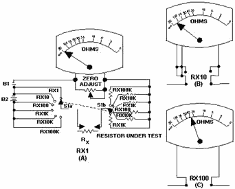
Figure 3-14. - Ohmmeter with multiplication switch. The range used to measure any particular unknown resistance (Rx in view a of figure 3-14)
depends on the approximate ohmic value of the unknown resistance. For instance, the ohmmeter scale of the figure
is calibrated in divisions from 0 to infinity. Note that the divisions are easier to read on the right-hand
portion of the scale than on the left. For this reason, if Rx is greater than 1,000 ohms and if you
are using the R x 1 range, you will be unable to accurately read the indicated resistance. This happens because
the combined series resistance of resistors Rx is too large for range R x 1 to allow enough battery
current to flow to deflect the pointer away from infinity. You need to turn the range switch to the R x 10
position to obtain the 1,000-ohm reading. Let's assume that you have changed the range switch to the R x
10 position and the pointer now deflects to a reading of 375 ohms, as shown in view B of figure 3-14. This would
indicate to you that unknown resistance Rx has 3,750 (375 times 10) ohms of resistance. The change of range
caused the deflection because resistor R x 10 has only 1/10 the resistance of resistor R x 1. Therefore, selecting
the smaller series resistance allowed a battery current of sufficient value to cause a readable pointer
deflection. If the R x 100 range were used to measure the same 3,750 ohm resistor, the pointer would deflect still
further to the 37.5-ohm position, as shown in view C. This increased deflection would occur because resistor R x
100 has only 1/10 the resistance of resistor R x 10. Q-23. The R x 100 resistance selection on an
ohmmeter has what amount of resistance compared to the R x 10 selection? The circuit arrangement in view a of
figure 3-14 allows the same amount of current to flow through the moving meter coil. The same amount is allowed to
flow whether the meter measures 10,000 ohms on the R x 1 scale, 100,000 ohms on the R x 10 scale, or 1,000,000
ohms on the R x 100 scale.
3-20
| - |
Matter, Energy,
and Direct Current |
| - |
Alternating Current and Transformers |
| - |
Circuit Protection, Control, and Measurement |
| - |
Electrical Conductors, Wiring Techniques,
and Schematic Reading |
| - |
Generators and Motors |
| - |
Electronic Emission, Tubes, and Power Supplies |
| - |
Solid-State Devices and Power Supplies |
| - |
Amplifiers |
| - |
Wave-Generation and Wave-Shaping Circuits |
| - |
Wave Propagation, Transmission Lines, and
Antennas |
| - |
Microwave Principles |
| - |
Modulation Principles |
| - |
Introduction to Number Systems and Logic Circuits |
| - |
- Introduction to Microelectronics |
| - |
Principles of Synchros, Servos, and Gyros |
| - |
Introduction to Test Equipment |
| - |
Radio-Frequency Communications Principles |
| - |
Radar Principles |
| - |
The Technician's Handbook, Master Glossary |
| - |
Test Methods and Practices |
| - |
Introduction to Digital Computers |
| - |
Magnetic Recording |
| - |
Introduction to Fiber Optics |
| Note: Navy Electricity and Electronics Training
Series (NEETS) content is U.S. Navy property in the public domain. |
|


