Module 16 - Introduction to Test Equipment
Pages i,
1-1,
1-11,
1-21,
2-1,
2-11,
2-21,
3-1,
3-11,
3-21,
3-31,
4-1,
4-11,
4-21,
5-1,
5-11,
5-21,
5-31,
6-1,
6-11,
6-21,
6-31,
6-41, Index
Capacitance
MEASUREMENTS
Capacitance measurements are usually taken with a capacitance meter. Capacitance tolerances vary even more widely
than resistance tolerances. Capacitance tolerances depend on the type of capacitor, the value of capacitance, and
the voltage rating. The actual measurement of capacitance is very simple; however, you must make the important
decision of whether to reject or to continue to use the capacitor after it has been tested. The Power
FACTOR of a capacitor is important because it is an indication of the various losses of a capacitor. Power losses
can be traced to the dielectric, such as current leakage and dielectric absorption. Current leakage is of
considerable importance, especially in electrolytic capacitors. Q-17. What is the term used to refer to
the losses which can be traced to the dielectric of a capacitor? Inductance MEASUREMENTS
Inductance measurements are seldom required in The Course of troubleshooting. However, inductance measurements are useful in some cases; therefore, bridges (discussed in the next section) are available for making this test. You
will find that many capacitance test sets can be used to measure inductance. Most capacitance test sets are
furnished with inductance conversion charts if the test equipment scale is not calibrated to read the value of
inductance directly.
Capacitance, Inductance, and Resistance BRIDGES You can measure capacitance, inductance,
and resistance for precise accuracy by using ac bridges. These bridges are composed of capacitors, inductors, and
resistors in a wide variety of combinations. These bridges are operated on the principle of a dc bridge called a
WHeatSTONE BRIDGE. Wheatstone Bridge The Wheatstone bridge is widely used for
precision measurements of resistance. The circuit diagram for a Wheatstone bridge is shown in figure 1-5.
Resistors R1, R2, and R3 are precision, variable resistors. The value of Rx is an unknown value of resistance
that must be determined. After the bridge has been properly balanced (galvanometer G reads zero), the unknown
resistance may be determined by means of a simple formula. The galvanometer (an instrument that measures small
amounts of current) is inserted across terminals b and d to indicate the condition of balance. When the bridge is
properly balanced, no difference in potential exists across terminals b and d; when switch S2 is closed, the
galvanometer reading is zero.
1-21

Figure 1-5. - Wheatstone bridge. The operation of the bridge is explained in a few logical steps. When the battery switch S1 is closed,
electrons flow from the negative terminal of the battery to point a. Here the current divides as it would in any
parallel circuit. Part of it passes through R1 and R2; the remainder passes through R3 and Rx. The two
currents, I1 and I2, unite at point c and return to the positive terminal of the battery.
The value of I1 depends on the sum of resistance R1 and R2, and the value of I2 depends on the sum of
resistances R3 and Rx. In each case, according to Ohm's law, the current is inversely proportional to
the resistance.
R1, R2, and R3 are adjusted so that when S1 is closed, no current flows through G. When the galvanometer shows no
deflection, there is no difference of potential between points b and d. All of I1 follows the a b c
path and all I2 follows the a b c path. This means that a voltage drop E1 (across R1
between points a and b) is the same as voltage drop E3 (across R3 between points a and d). Similarly,
the voltage drops across R2 and Rx (E2 and Ex) are also equal. Expressed
algebraically,

and

With this information, we can figure the value of the unknown resistor Rx. Divide the voltage
drops across R1 and R3 by their respective voltage drops across R2 and Rx as follows:

We can simplify this equation:

1-22
then we multiply both sides of the expression by Rx to separate it:

For example, in figure 1-5, we know that R1 is 60 ohms, R2 is 100 ohms, and R3 is 200 ohms. To find the
value of Rx, we can use our formula as follows:

Use of ac Bridges A wide variety of ac bridge circuits (such as the Wheatstone)
may be used for the precision measurement of ac resistance, capacitance, and inductance. Let's look at ac bridges
in terms of functions they perform. Resistance BRIDGE. - An ac signal generator, as shown in figure 1-6, is used as the source of
voltage. Current from the generator passes through resistors R1 and R2, which are known as the ratio arms, and
through Rs and Rx. Again, Rx is known as resistance. Rs has a
standard value and replaces R3 in figure 1-6. When the voltage drops across R2 and Rs are equal, the
voltage drops across R2 and Rx
are also equal; no difference of potential exists across the meter and no current flows through it. As we
discovered with the Wheatstone bridge, when no voltage appears across the meter, the following ratio is true:
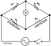
Figure 1-6. - Resistance bridge (ac). For example, if in figure 1-6 we know that R1 is 20 ohms, R2 is 40 ohms, and Rs is 60 ohms,
we can find the value of Rx using our formula as follows:
1-23

With the ac signal applied to the bridge, R1 and R2 are varied until a zero reading is seen on the
meter. Zero deflection indicates that the bridge is balanced. (Note: In actual practice, the
variables are adjusted for a minimum reading since the phase difference between the two legs will not always allow
a zero reading.)
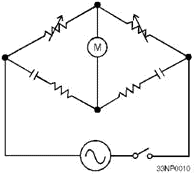
Capacitance BRIDGE. - Because current varies inversely with resistance and directly with
capacitance, an inverse proportion exists between the four arms of the bridge in figure 1-7; the right side of our
expression is inverted from the resistance bridge expression as follows:

or


Figure 1-7. - Capacitance bridge. Q-18. What effect does an increase in capacitance have on a capacitor's opposition to current flow?
Because R1 and R2 are expressed in the same units, the equation R1/R2 becomes a simple multiplication factor.
This equation provides a numerical value for Cx and will be in the same units as Cs
(farad, microfarad, and so forth).
1-24
Similarly, the following resistance ratio exists between the four arms of the bridge, just as in the
resistance bridge expression discussed earlier:

or

Thus, both the unknown resistance and capacitance, Rx and Cx, can be estimated
in terms of known resistance R1, R2, Rs, and known capacitance Cs.
In figure 1-7, for example, we know that R1 is 20 ohms, R2 is 40 ohms, Rs is 60 ohms, and Cs is 10
microfarads. We can find the values of Cx and Rx by using the respective formulas as
follows:

and

Q-19. When a bridge is used to measure resistance, what is the value of Rx if R1 equals 80
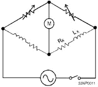
ohms, R2 equals 120 ohms, and R3 equals 280 ohms? Inductance BRIDGE. - The value of the
unknown inductance Lx may be determined by means of the simple bridge circuit shown in figure 1-8. Ratio arms R1
and R2 are accurately calibrated resistors. Ls is a standard inductor with a known inductance; Rs is
the known resistance, and Rx represents the resistance of the unknown inductor.
1-25
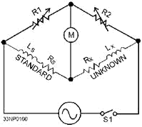
Figure 1-8. - Inductance bridge. The ac signal is applied to the bridge, and variable resistors R1 and R2 are adjusted for a minimum or
zero deflection of the meter, indicating a condition of balance. When the bridge is balanced, the following
formulas may be used to find Lx. (Note: The right side of this expression is NOT inverse as it
was in the capacitance bridge.)

and

or

In figure 1-8, for example, the values of R1, R2, and Rs are 20, 40, and 60 ohms,
respectively. The value of Ls is 10 millihenries. We can find the values of Rx and Lx
by using their respective formulas as follows:

and

Thus, both the unknown resistance and inductance can be estimated in terms of the known values for
R1, R2, Rs, and Ls. Q-20. When an unknown capacitance is tested with a bridge,
what is the value of Cx if R1 equals 70 ohms, R2 equals 150 ohms, and Cs equals 550 microfarads?
Summary The important points of this chapter are summarized in the following paragraphs: The
JETDS System is jointly used by all branches of the military to identify equipments by a system
of standardized nomenclatures. GPETE is test equipment that has the capability, without
modifications, to generate, modify, or measure a range of parameters of electronic functions required to test two
or more equipments or systems of basically different design. All GPETE are listed in Standard General Purpose
Electronic Test Equipment, MIL-STD-1364 (series). SPETE is test equipment that is
specifically designed to generate, modify, or measure a range of parameters of electronic functions of a specific
or peculiar nature required to test a single equipment or system. The SHIP Configuration and
LOGIsTICS INforMATION System (SCLSIs) program is designed to keep track of equipment configuration
changes in the fleet.
The SCLSIs program has two basic elements, VALIDATION and INVENTORY UPDATING. The
CALIBRATION STATUS of any items of test equipment can be determined by the information recorded
on the calibration label or tag located on the equipment.
1-27

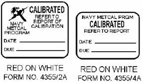
The CALIBRATED label, with black lettering on a white background, indicates the
instrument to which it is attached is within tolerance on all scales. The CALIBRATED - REFER to
REPORT
label, with red lettering on a white background, is used when actual measurement values must be known to use the
instrument.
 The Special CALIBRATION label, with black lettering on a yellow background, is used
when some unusual or special condition in the calibration should be drawn to your attention.
1-28

The useR CALIBRATION label indicates that you should calibrate the test and measuring
instrument instead of sending the instrument to a calibration facility.
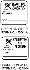
 The INACTIVE - CALIBRATE BEforE use label is used when a piece of test equipment due for
recalibration will not be used for some time in the future. The CALIBRATION NOT REQUIRED
label is used on test instruments listed in the Metrology Requirements List (METRL) as not requiring calibration.
1-29
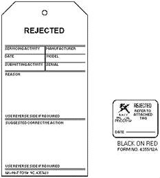
 The REJECTED label is attached to a test instrument that fails to meet the acceptance
criteria during calibration and cannot be repaired.
1-30
The CALIBRATION VOID IF SEAL BROKEN label is placed over readily accessible
adjustments to prevent tampering by the user when such tampering could affect the calibration.
 The MEASURE system is designed to standardize the recall and scheduling of test,
measurement, and diagnostic equipment into calibration facilities and for the documentation of actions performed
by the calibration facility. Maintenance is work done to correct, reduce, or counteract
wear and damage to equipment. PREVENTIVE Maintenance consists of checks to determine
weather equipment is functioning properly. It also consists of visual inspections of cabling and equipment for
damage and to determine if lubrication is needed. CORRECTIVE Maintenance is used to
isolate troubles by means of test techniques and practices that realign or readjust equipment or otherwise bring
the equipment back up to proper performance. SENSITIVITY of the voltmeter is always given
on the voltage charts for a particular piece of equipment. You should always use a voltmeter of similar
sensitivity to the equipment to diminish the effects of circuit loading. CURRENT MEASUREMENTS
are not often taken in The Course of testing because the ammeter (or other current measuring device) must become
an actual part of the equipment being tested. The circuit must be opened for necessary connection of the meter.
Usually you can use a voltage measurement to calculate the circuit current by applying Ohm's law. You
should observe the following PRECautionS when using an ohmmeter: 1. The circuit being tested must be
completely de-energized.
2. Any circuit components which can be damaged by ohmmeter current must be removed before any measurement is
made. The WHeatSTONE BRIDGE is used for precise measurement of resistance.
1-31

The Capacitance BRIDGE is used for measuring an unknown capacitance.
An Inductance BRIDGE is used to find the value of an unknown inductance.
1-32
Answers to Questions Q1. Through Q20. A-1. Joint Electronics Type Designation System (JETDS). A-2. General-purpose electronic test
equipment (GPETE) and special-purpose electronic test equipment (SPETE). A-3. Special-purpose electronic
test equipment. A-4. Validation and updating. A-5. CALIBRATED - REFER to REPORT. A-6.
Special CALIBRATION label. A-7. Maintenance personnel. A-8. The Chief of Naval Operations.
A-9. Preventive and corrective maintenance. A-10. Corrective maintenance. A-11.
Current. A-12. Shorting probe. A-13. Highest. A-14. Ground. A-15. In
series. A-16. It must be de-energized.
A-17. Power losses. A-18. Opposition to current flow decreases.
A-19. 420 ohms. A-20. 256 microfarads.
1-33
| - |
Matter, Energy,
and Direct Current |
| - |
Alternating Current and Transformers |
| - |
Circuit Protection, Control, and Measurement |
| - |
Electrical Conductors, Wiring Techniques,
and Schematic Reading |
| - |
Generators and Motors |
| - |
Electronic Emission, Tubes, and Power Supplies |
| - |
Solid-State Devices and Power Supplies |
| - |
Amplifiers |
| - |
Wave-Generation and Wave-Shaping Circuits |
| - |
Wave Propagation, Transmission Lines, and
Antennas |
| - |
Microwave Principles |
| - |
Modulation Principles |
| - |
Introduction to Number Systems and Logic Circuits |
| - |
- Introduction to Microelectronics |
| - |
Principles of Synchros, Servos, and Gyros |
| - |
Introduction to Test Equipment |
| - |
Radio-Frequency Communications Principles |
| - |
Radar Principles |
| - |
The Technician's Handbook, Master Glossary |
| - |
Test Methods and Practices |
| - |
Introduction to Digital Computers |
| - |
Magnetic Recording |
| - |
Introduction to Fiber Optics |
| Note: Navy Electricity and Electronics Training
Series (NEETS) content is U.S. Navy property in the public domain. |
|


