Module 21 - Test Methods and Practices
Pages i ,
1-1,
1-11,
1-21,
2-1,
2-11,
2-21,
2-31,
2-41,
3-1,
3-11,
3-21,
3-31,
4-1,
4-11,
5-1,
5-11,
5-21,
5-31, AI-1 to AI-3, Index
Chapter 1
Basic MEASUREMENTS
Learning Objectives Learning objectives are stated at the beginning of each chapter. These learning objectives serve as a
preview of the information you are expected to learn in the chapter. The comprehensive check questions and answers
are based on the objectives and enable you to check your progress through the reading assignments. By successfully
completing the OCC/ECC, you demonstrate that you have met the objectives and have learned the information. The
learning objectives for this chapter are listed below. Upon completion of this chapter, you will be able
to do the following: 1. Explain the importance of performing basic electronic measurements.
2. Explain the importance of voltage measurements in troubleshooting. 3. Identify the various
methods of performing voltage measurements. 4. Identify the various methods of performing current
measurements. 5. Identify the various methods of performing resistance measurements. 6.
Identify the various methods of performing capacitance measurements. 7. Identify the various methods of
measuring inductance.
Introduction to MEASUREMENTS In today's modern Navy, a large part of a ship's, submarine's, or aircraft's ability to complete its
mission depends on the efficiency of sophisticated electronic systems. As the technician responsible for these
systems, you are the focal point in ensuring their reliability. In the event of a system failure, it is your
responsibility to repair the system and to do so in a timely manner. Whether you are troubleshooting a faulty
system or performing preventive maintenance, you are required to perform basic electronic measurements on a
regular basis. This chapter will acquaint you with various alternative methods of performing measurements and
discuss the relative merits and demerits of each method. No discussion of electronic test equipment or
electronic measurements would be complete without mentioning the Navy's Metrology Calibration (METCAL) program.
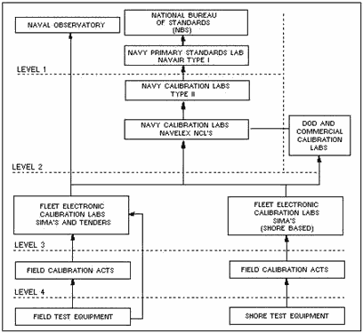
Figure 1-1 shows the METCAL structure. Basically, the METCAL program is an elaborate quality control system
designed to compare your electronic test equipment with test equipment of much greater accuracy. When you submit
your piece of test equipment for calibration, it is compared with the calibration laboratory's equipment (referred
to as STANDARDS), which are generally at least four times more accurate than yours. If your equipment does not
meet specifications, it is either repaired, adjusted, or rejected with an explanation of why the calibration
laboratory was unable to calibrate it. The accuracy of equipment at your local calibration laboratory is ensured
by calibration of the test equipment to the standards of the next higher echelon calibration laboratory. The
accuracies of test equipment at each higher echelon is increased by a ratio of approximately 4 to 1.

Figure 1-1. - Calibration laboratory structure. METCAL provides assurance that your test equipment is in top-notch shape. Remember, your measurements
are only as accurate as your test equipment; be fully aware of the limitations of your test equipment and never use equipment that isn't properly calibrated when performing measurements or adjustments. Q-1. What
assures the accuracy of your electronic test equipment? Now that we have discussed the advantages of
calibrated test equipment, let's review the reason for all this concern. The fundamental electrical quantities of
a circuit are voltage and current and are dependent on the circuit characteristics of resistance, capacitance, and
inductance. In addition to these three individual characteristics, don't forget that many electronic components
exhibit more than one circuit characteristic at the same time. An example would be a piece of coaxial cable that
is engineered by its manufacturer to meet characteristic specifications for impedance, capacitance, and
inductance. But let's keep it simple and begin by covering voltage measurements.
Operation and use of common test equipment was covered in NEETS Module 16, Introduction to Test
Equipment, NAVEDTRA B72-16-00-95. It is recommended that you review this module before continuing.
Voltage MEASUREMENTS Most Navy technical manuals provide voltage charts that list correct voltages at all primary test points
in a piece of equipment. Voltage measurements, when compared with these charts, provide a valuable aid in locating
troubles quickly and easily. However, if the sensitivity of the test equipment differs from that of the test
equipment used in preparing the chart, the voltage measurements may not reflect true circuit conditions. You must
keep in mind that a voltmeter with low sensitivity used on a low range may disturb circuits under test or provide
a false indication. Most technical manuals will tell you what type and model of test equipment was used to prepare
the voltage charts. As a rule of thumb, the input impedance of the voltmeter should exceed the impedance of the
circuit by a ratio of at least 10 to 1. Technicians have spent uncounted hours of wasted time because they have
selected improper test equipment.
Q-2. The input impedance of your test equipment should exceed the impedance of the circuit under test by what
ratio? DC Voltage MEASUREMENTS Direct current voltage may be steady, pulsating, or have ac
superimposed on it. The average value of a dc waveform depends on the symmetry of the wave and other aspects of
the wave shape. It can vary from 63.6% of peak value for a rectified full sine wave to 50% of peak value for a
triangular wave. For a superimposed sine wave, the average value can be zero. Regardless of whether the dc is
steady, pulsating, or the ac is superimposed on the dc, a rectifier form of measuring device will indicate its
average value.
Voltages are usually measured by placing the measuring device in parallel with the component or circuit (load) to
be measured. The measuring device should have an infinite internal resistance (input impedance) so that it will
absorb no energy from the circuit under test and, therefore, measure the true voltage. The accuracy of the voltage
measurement depends on the total resistance of the measuring device compared to the load being measured. When the
input impedance of the measuring device is 10 times greater than the load being measured, the error usually can be
tolerated. If this error cannot be tolerated, a high input impedance measuring device, such as a vacuum tube
voltmeter (vtvm), should be used. Alternatively, using two voltmeters in series increases the voltage range and,
because of the increase in total voltmeter resistance, provides a more accurate measurement of voltage across the
load. If the voltage to be measured is sufficiently high, more than two similar voltmeters can be connected in
series across the load to provide greater accuracy; the total voltage measurement is the sum of the individual
meter indications. Q-3. What are the advantages of using two voltmeters in series?
Multimeter Method
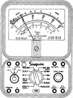
a common piece of test equipment used in the Navy is the Simpson 260 analog multimeter, as shown in figure 1-2. It
is capable of measuring both ac and dc voltages of up to 5,000 volts.

Figure 1-2. - Simpson 260 multimeter. Two obvious advantages of the Simpson 260 are its portability and ease of operation. Among its
disadvantages are its low input impedance and the inherent low accuracy associated with D'Arsonval meter
movements, which are used in the meter. When performing measurements with any analog multimeter, remember that the
most accurate readings are taken with the pointer midscale. You should also be aware of inaccuracies introduced as
a result of parallax. PARALLAX is defined as the apparent displacement of the position of an object because of the
difference between two points of view. In the case of meters, this means the position of a meter's pointer will
appear to be at different positions on the scale depending on the angle from which the meter is viewed. Some of
the Simpson 260 and 270 series multimeters have effectively eliminated the problem of parallax by incorporating a
mirror on the scale that accurately reflects the position of the pointer of the meter movement. Q-4. At
what point on a meter movement are the most accurate readings taken? Oscilloscope Method
A dc voltage measurement can be made with an oscilloscope, as shown in figure 1-3, that has a direct-coupled
deflection amplifier or terminals for connection directly to the deflection plates of the cathode-ray tube.
Measuring a dc voltage with an oscilloscope is convenient only under certain circumstances; for example, when
other measurements are being made on the same equipment with the oscilloscope or when a vacuum tube voltmeter is
not available and a high-impedance measuring device is required.

Figure 1-3. - Dual-trace oscilloscope. Oscilloscopes have a high input impedance and normally will not load down the circuit under test.
However, oscilloscopes are primarily designed for waveform observation and are typically less accurate than other
pieces of test equipment used to measure dc voltages. a distinct advantage of the oscilloscope is its ability to
monitor the level of ac ripple voltage riding the dc voltage. This feature makes the oscilloscope an indispensable
aid in troubleshooting dc power supplies with excessive ripple caused by component failure.
Digital Multimeter Method
Most analog voltmeters (that use D'Arsonval meter movements) in common use today are accurate to approximately ±2%
of full-scale reading. Most digital multimeters, as shown in figure 1-4, have a high input impedance and are not
likely to disturb the circuit being tested. The digital multimeter in most cases provides an accuracy of at least
±0.1%.

Figure 1-4. - Digital multimeter. Digital multimeters display the reading numerically. These direct-reading displays, along with automatic
range- and polarity-changing features, eliminate the problem of parallax, reduce error and tedium, and increase
measurement speed. Data from these meters in digital format can also be processed
by computers, printers, tape and card punches, and magnetic-tape equipment. Digital multimeters are
typically compact and lightweight; many come with rechargeable batteries, making them ideal for portable field use. The disadvantages are that they are not rugged and will not tolerate abuse and that some models do not
produce sufficient bias voltage to test a diode or transistor junction. The John Fluke Model 77 A/N digital
multimeter is presently being purchased by the Navy and will eventually phase out the older and less accurate
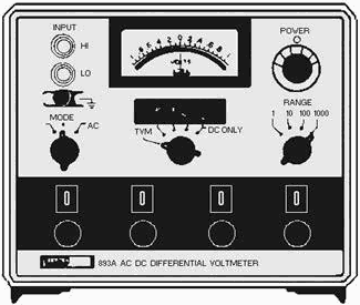
analog meters. Differential Voltmeter Method Using the differential voltmeter, as
shown in figure 1-5, provides one of the most accurate methods of measuring dc voltage. Typical accuracies
attained by this method are ±0.005%. These extremely high accuracies are achieved by the design of the voltmeter
with precision internal reference voltages and precision resistors. As discussed earlier in NEETS, module 6,
Introduction to Electronic Emission, Tubes, and Power Supplies, most differential voltmeters can be operated as
transistor voltmeters (tvm) or as differential null voltmeters. The tvm mode is used to measure the approximate
voltage and polarity of the unknown voltage being measured. The approximate voltage, as measured in the tvm mode,
is then used to make the initial range and mode switch selections for nulling the input voltage.

Figure 1-5. - Ac-dc differential voltmeter. The advantages of using a differential voltmeter for measuring dc voltages are the extreme accuracy and
minimal circuit loading made possible by the high input impedance of the meter. However, differential voltmeters
are less portable, heavier, and require greater skill and time when performing measurements than other types of
voltmeters. Additionally, they require long warm-up periods and are susceptible to variations in temperature and
humidity.
Q-5. What are the advantages of using a differential voltmeter?
AC Voltage MEASUREMENTS When ac voltage measurements are performed, the input
impedance of the selected test equipment determines the amount of energy removed from the circuit under test. If
an ac meter is placed across a high-impedance circuit, the meter may load the high-impedance circuit and disturb
circuit conditions, possibly to the point of causing the circuit to cease functioning. a dc electronic voltmeter, used in conjunction with a rectifying probe, extracts only a small amount of energy from the circuit under test.
Another advantage of an electronic voltmeter over the analog voltmeter is that voltages of low values can be
accurately measured.
If the circuit being measured is a relatively high-frequency circuit, the internal capacitance of an analog
voltmeter rectifier could produce a disturbance by detuning the circuit. Figure 1-6 depicts the frequency response
of a Simpson 260. Note the percent of error introduced at different frequencies. For high-frequency voltage
measurements, an electronic voltmeter or an oscilloscope should be used. The sensitivity of the meter (or
oscilloscope) determines the lowest voltage it can measure accurately, and the shunt capacitance of its input
determines the upper frequency limits. It should be clear that the frequency response of a piece of test equipment
is just as important as its range limitations. If you exceed the range limitations of a meter, it will either
"peg" the meter or belch out the smell of smoke that many of us are intimately acquainted with. This, however, is
not the case when you exceed the frequency limitations of your test equipment. Your test equipment will normally
show a response, but that response will be grossly inaccurate. The lesson to be learned here is that you should be
fully aware of the limitations of your test equipment and adhere to them.

Figure 1-6. - Simpson 260 frequency response for ac voltage ranges.
Q-6. The frequency response of test equipment refers to what aspect of ac voltage measurements?
Multimeter Method As previously stated, an analog multimeter's usefulness is limited by
its low input impedance and poor accuracy (typically ±2%). However, rugged construction and ease of operation make
analog multimeters extremely useful whenever poor accuracy and low input impedance can be tolerated. When
performing ac voltage measurements with a multimeter, be certain that the frequency of the signal being measured
falls within the upper and lower frequency limitations of the meter. Oscilloscope Method
a major advantage of using an oscilloscope for ac voltage measurements is that the waveform can be observed;
consequently, errors in measuring complex peak voltages are minimized. An oscilloscope may be used as a
high-impedance ac voltmeter. In standard oscilloscopes, the vertical amplifier input impedance is generally
greater than 1 megohm, making it possible to measure voltages in high-impedance circuits. If the signal is applied
directly to the plates, rather than at the vertical amplifier input, the input impedance is increased
considerably. Voltage measurements are most easily made when the deflection of the trace extends across
the major portion of the oscilloscope screen; whenever possible, the trace should cover at least 60% of the
vertical viewing area of the screen. If the amplitude of the measured voltage is very low, the trace dimensions
may be small. If a voltage to be measured is large and cannot be attenuated to a usable value by attenuation
circuits within the oscilloscope, an external resistive or capacitive voltage divider can be used. Such voltage
dividers are often furnished with oscilloscope test sets and are called High Voltage PROBES. When the voltage of
pulses or other complete waveforms is being measured, the high voltage probe selected must be so designed as not
to distort the measured signal. Most probes have adjustable (compensating) capacitors that are used to adjust the
symmetry of the displayed waveform. You adjust the probe by monitoring either the calibrator output of the
oscilloscope or a known good signal and adjusting the probe for a symmetrical display. Oscilloscopes are
calibrated to display peak-to- peak values. To determine the rms voltage of a sinusoidal signal, divide the number
of graticule units from the positive to the negative peaks by two and multiply this value by 0.707. When using the
oscilloscope for ac voltage measurements, ensure the upper frequency range of the oscilloscope is not exceeded;
otherwise, inaccurate values will be displayed. Most commonly used oscilloscopes have a frequency response from dc
up to 100 megahertz. Q-7. Ideally, an oscilloscope presentation should cover what vertical portion of
the screen? Digital Multimeter Method As previously mentioned, digital
multimeters present a high input impedance to the circuit under test and are fairly accurate. Many earlier models
had very limited frequency responses. Even today the upper frequency limitations of digital multimeters vary from
20 kilohertz to over 300 kilohertz, depending on the model. Their upper frequency limitations can, however, be
significantly extended by using optional RF probes. When you perform ac voltage measurements with a digital
multimeter, remember that they are true rms indicating devices. Differential Voltmeter Method
Most differential voltmeters can be used to measure both ac and dc voltages. The differential voltmeter method of
measuring ac voltage is the most accurate of the common measurement techniques. Typical accuracies are ±0.05% when
operated in the ac mode.
CURRENT MEASUREMENTS Unless an ammeter is already an integral part of the circuit under test, current measurements are rarely
taken. In the case of a high-resistance circuit, it will contain such a small amount of current that it cannot be
measured accurately with ordinary field test equipment. In lower resistance circuits, current measurements can be
taken only if the ammeter is placed in series with the circuit under test. These measurements require that a
circuit connection be unsoldered or otherwise opened to insert the meter in series with the circuit. An easier
method you may use to obtain a current measurement is to take a voltage measurement across a known resistance and
calculate the current with Ohm's law. The accuracy of current measurements depends on the internal resistance of
the meter as compared with the resistance of the external circuit. If the total circuit current is decreased by
increasing the load, then the percentage of error will decrease. Therefore, greater accuracy is obtained if the
meter resistance is considerably less than the load resistance. a method of obtaining greater accuracy of current
measurement is to decrease the total internal meter resistance with respect to load resistance. This is
accomplished by connecting two ammeters in parallel with each other and in series with the circuit in which the
current is being measured. Additional ammeters may be connected in parallel in the same manner for increased
accuracy. This method also increases the range of measurements that can be taken. The arithmetical sum of the
indications of all the parallel meters represents the total current flow in the circuit. You should note that this
is not a common test method and that your test equipment may be damaged if connected incorrectly.
MULTIMETER METHOD As previously mentioned, current measurements are usually taken by breaking the
current path of the circuit under test and electrically inserting a meter in series. This is normally accomplished
by disconnecting a wire from a terminal or unsoldering one end of a component and electrically inserting the meter
in series using the meter leads. This method is both time consuming and usually requires the use of a soldering
iron, which can damage components. Most analog multimeters cannot be used for measuring ac current and are only
accurate to within ±2% on dc ranges. Q-8. What are the advantages of connecting ammeters in parallel
when performing current measurements? DIGITAL MULTIMETER METHOD Unlike the analog
multimeter, the digital multimeter will measure ac current as well as dc current. Again, current measurements are
taken by breaking the current path and inserting the meter in series. Regardless of whether you're using an analog
multimeter or digital multimeter, this procedure for measuring current is time consuming. However, there is a
major advantage to be gained by using the digital multimeter - its high degree of accuracy. The Fluke 8000A
digital multimeter, for example, is accurate to within ±0.3% when measuring dc current and ±1% when measuring ac
current. These accuracies are representative of most medium-priced digital multimeters.
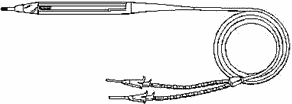
CURRENT TRACERS For the purpose of discussion, we have selected the Hewlett-Packard 547A,
shown in figure 1-7, as a representative current tracer. a current tracer will not actually measure current; it is
designed to indicate the presence of current and the relative magnitude of one source of current as compared to
another. The Hewlett-Packard 547A is a hand-held probe that enables you to precisely localize low-impedance faults
in a circuit. The probe senses the magnetic field generated by a pulsing current and lights an indicator lamp near
the current tracer tip. The brightness of the indicator lamp is proportional to the magnitude of the current. The
sensitivity of the indicator lamp can be adjusted with a thumb-wheel potentiometer located on the probe. Figure
1-8 depicts a typical logic circuit application for a current tracer. Current tracers are
ideally suited for locating shorted or opened printed-circuit-board runs, wires, or components. In the
absence of a suitable pulsing current to drive the current tracer, a logic pulser or pulse generator may be used
as a signal source. The inherent disadvantage of a current tracer is that it requires an external power supply.
They can, however, be connected to the power supply of the equipment under test if the voltage is correct.

Figure 1-7. - Current tracer.

Figure 1-8. - Current tracer application.
CURRENT PROBES Current probes, as shown in figure 1-9, are primarily designed to be used with an oscilloscope or
milliammeter for measuring current. Although not used very often by Navy technicians, current probes are
available. The primary advantage in using a current probe is that it does not need to be in series with the
current being measured. Unsoldering wires or connections to terminals is not necessary; current probes are
designed to be clamped onto insulated conductors. They are able to sense, through inductive action, the magnitude
of the current flowing in the conductor. Current probes are designed for performing small ac current measurements.
Also, when you use them in conjunction with current probe amplifiers, the capabilities of the current probe are
extended to measurement of both ac and dc currents with large magnitudes. Current probes are extremely useful when
you measure the current drain on a power supply, start-up current of a motor, or current flow in relays. These
probes can be divided into three basic types: passive, active, and Hall effect. Each type has advantages and
disadvantages peculiar to its method of operation. Prior to using a current probe, you should thoroughly
understand its instructions
| - |
Matter, Energy,
and Direct Current |
| - |
Alternating Current and Transformers |
| - |
Circuit Protection, Control, and Measurement |
| - |
Electrical Conductors, Wiring Techniques,
and Schematic Reading |
| - |
Generators and Motors |
| - |
Electronic Emission, Tubes, and Power Supplies |
| - |
Solid-State Devices and Power Supplies |
| - |
Amplifiers |
| - |
Wave-Generation and Wave-Shaping Circuits |
| - |
Wave Propagation, Transmission Lines, and
Antennas |
| - |
Microwave Principles |
| - |
Modulation Principles |
| - |
Introduction to Number Systems and Logic Circuits |
| - |
- Introduction to Microelectronics |
| - |
Principles of Synchros, Servos, and Gyros |
| - |
Introduction to Test Equipment |
| - |
Radio-Frequency Communications Principles |
| - |
Radar Principles |
| - |
The Technician's Handbook, Master Glossary |
| - |
Test Methods and Practices |
| - |
Introduction to Digital Computers |
| - |
Magnetic Recording |
| - |
Introduction to Fiber Optics |
| Note: Navy Electricity and Electronics Training
Series (NEETS) content is U.S. Navy property in the public domain. |
|


