|
|||||||||||||||||||||||||||||||||
 |
|||||||||||||||||||||||||||||||||
Bessel Filter Poles |
|||||||||||||||||||||||||||||||||
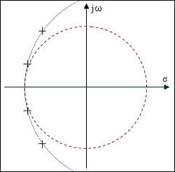
Bessel poles lie along a circle similar to the Butterworth filter, but are spaced approximately equal distances apart relative to the real axis rather than at equal angular distances. Prototype value real and imaginary pole locations (ω=1 at the 3dB cutoff point) for Bessel filters are presented in the table below.
This pole-zero diagram shows the location of poles for a 4th-order Bessel lowpass filter. Bessel filter prototype element values are here. Bessel function plots can be found here. Data taken from "Filter Design," by Steve Winder, Newnes Press, 1998. This is a great filter design book, and I recommend you purchase a copy of it. Related Pages on RF Cafe - Butterworth Filter Equations for Magnitude, Phase, and Group Delay - Chebyshev Filter Equations for Magnitude, Phase, and Group Delay - Butterworth Lowpass Filter Gain, Phase, and Group Delay Equations - Butterworth Highpass, Bandpass, & Bandstop Filter Gain, Phase, and Group Delay Equations - How to Use Filter Equations in a Spreadsheet - Filter Equivalent Noise Bandwidth - Filter Prototype Denormalization - Bessel Filter Prototype Element Values - Butterworth Lowpass Filter Poles - Butterworth Filter Prototype Element Values - Chebyshev Lowpass Filter Poles - Chebyshev Filter Prototype Element Values - Monolithic Ceramic Block Combline Bandpass Filters Design - Coupled Microstrip Filters: Simple Methodologies for Improved Characteristics |
|||||||||||||||||||||||||||||||||
|
|||||||||||||||||||||||||||||||||
|
|||||||||||||||||||||||||||||||||

|
||||||||||||||||||||||||||||||||||||


