|
||||||||||||||||||||||||||||||||||||||||||||||||||||||||||||||||||||||||||||||||||||||||||||||||||||||||||||||||||||||||||||||||||||||||||||||||||||||||||||||||||||||||||||||||||||||||||||||||||||||||||||||||||||||||||||||||||||||||||||||||||||||||||||||||||||||||||||||||||||||||||||||||||||||||||||||||||||||||||||||||||||||||||||||||||||||||||||||||||||||||||||||||||||||||||||||||||||||||||||||||||||||||||||||||||||||||||||||||||||||||||||||||||||||||||||||||||||||||||||||||||||||||||||||||||||||||||||||||||||||||||||||||||
 |
||||||||||||||||||||||||||||||||||||||||||||||||||||||||||||||||||||||||||||||||||||||||||||||||||||||||||||||||||||||||||||||||||||||||||||||||||||||||||||||||||||||||||||||||||||||||||||||||||||||||||||||||||||||||||||||||||||||||||||||||||||||||||||||||||||||||||||||||||||||||||||||||||||||||||||||||||||||||||||||||||||||||||||||||||||||||||||||||||||||||||||||||||||||||||||||||||||||||||||||||||||||||||||||||||||||||||||||||||||||||||||||||||||||||||||||||||||||||||||||||||||||||||||||||||||||||||||||||||||||||||||||||||
Chebyshev Filter Lowpass Prototype Element Values |
||||||||||||||||||||||||||||||||||||||||||||||||||||||||||||||||||||||||||||||||||||||||||||||||||||||||||||||||||||||||||||||||||||||||||||||||||||||||||||||||||||||||||||||||||||||||||||||||||||||||||||||||||||||||||||||||||||||||||||||||||||||||||||||||||||||||||||||||||||||||||||||||||||||||||||||||||||||||||||||||||||||||||||||||||||||||||||||||||||||||||||||||||||||||||||||||||||||||||||||||||||||||||||||||||||||||||||||||||||||||||||||||||||||||||||||||||||||||||||||||||||||||||||||||||||||||||||||||||||||||||||||||||
|
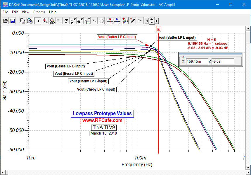
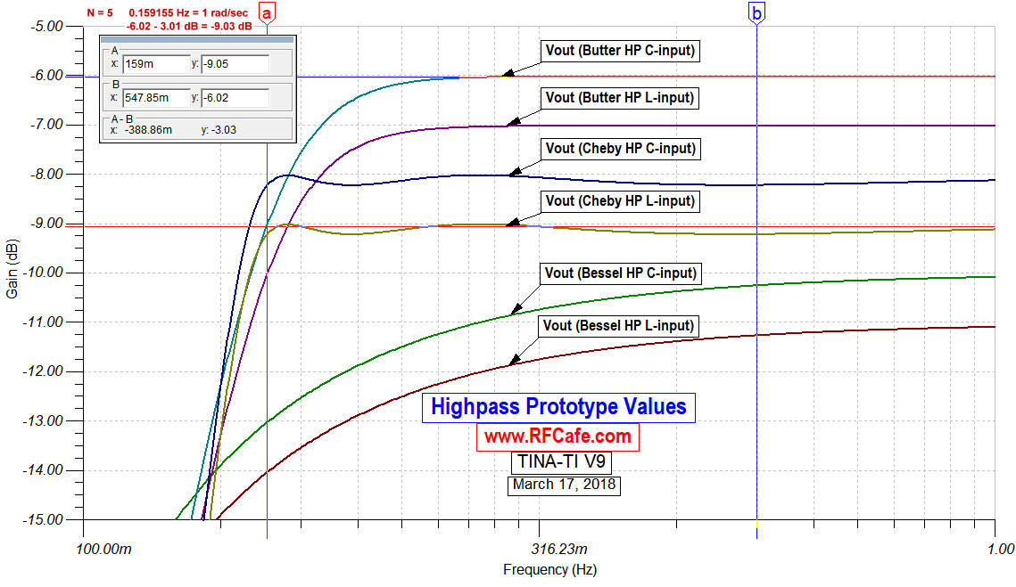
Simulations of Normalized and Denormalized LP, HP, BP, and BS Filters
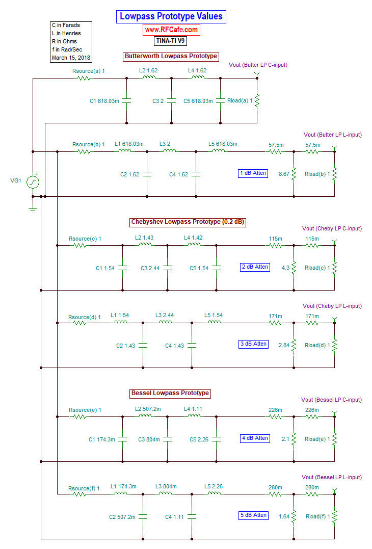
Lowpass Filters (above)
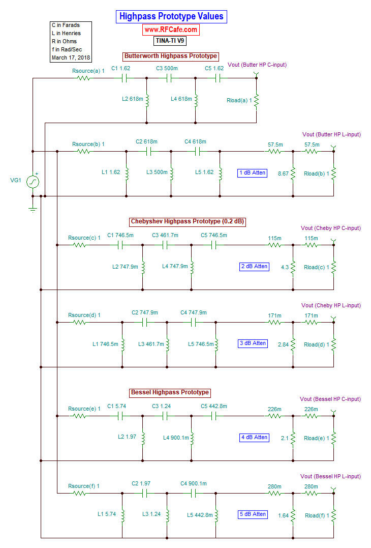
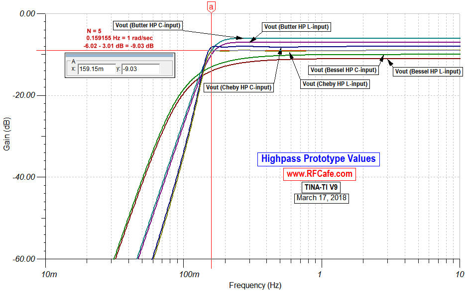
Highpass Filters (above)
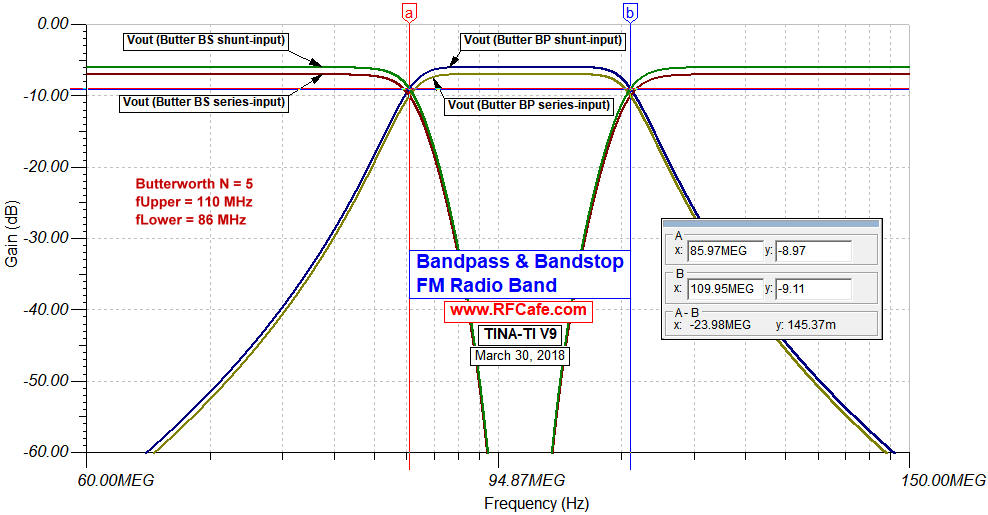
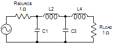
Bandpass and Bandstop Filters (above) The table below lists prototype element values for the normalized lowpass function, which assumes a cutoff frequency of 1 rad/sec and source and load impedances of 1 Ω. Either an input capacitor (top title line in table) or an input inductor (bottom title line in table) can be used. Note that for even order filters, the 0 Hz (DC) insertion loss is equal to the ripple value. Convert values to other cutoff frequencies, impedances, and to highpass, bandpass or bandstop using denormalization equations. Complex poles are here.
* Note: In the tables below of normalized Chebyshev filter components values, the right-most column is labeled "RLoad." This is necessary because even-order Chebyshev filters are not realizable when the source and termination impedances are exactly equal. A scaling factor is included for the termination impedance as shown. Normalized Chebyshev element values, 0.01 dB ripple*
Normalized Chebyshev element values, 0.1 dB ripple*
Normalized Chebyshev element values, 0.20 dB ripple*
Normalized Chebyshev element values, 0.5 dB ripple*
Related Pages on RF Cafe - Butterworth Filter Equations for Magnitude, Phase, and Group Delay - Chebyshev Filter Equations for Magnitude, Phase, and Group Delay - Butterworth Lowpass Filter Gain, Phase, and Group Delay Equations - Butterworth Highpass, Bandpass, & Bandstop Filter Gain, Phase, and Group Delay Equations - How to Use Filter Equations in a Spreadsheet - Filter Equivalent Noise Bandwidth - Filter Prototype Denormalization - Bessel Filter Prototype Element Values - Butterworth Lowpass Filter Poles - Butterworth Filter Prototype Element Values - Chebyshev Lowpass Filter Poles - Chebyshev Filter Prototype Element Values - Monolithic Ceramic Block Combline Bandpass Filters Design - Coupled Microstrip Filters: Simple Methodologies for Improved Characteristics |
||||||||||||||||||||||||||||||||||||||||||||||||||||||||||||||||||||||||||||||||||||||||||||||||||||||||||||||||||||||||||||||||||||||||||||||||||||||||||||||||||||||||||||||||||||||||||||||||||||||||||||||||||||||||||||||||||||||||||||||||||||||||||||||||||||||||||||||||||||||||||||||||||||||||||||||||||||||||||||||||||||||||||||||||||||||||||||||||||||||||||||||||||||||||||||||||||||||||||||||||||||||||||||||||||||||||||||||||||||||||||||||||||||||||||||||||||||||||||||||||||||||||||||||||||||||||||||||||||||||||||||||||||
 |
||||||||||||||||||||||||||||||||||||||||||||||||||||||||||||||||||||||||||||||||||||||||||||||||||||||||||||||||||||||||||||||||||||||||||||||||||||||||||||||||||||||||||||||||||||||||||||||||||||||||||||||||||||||||||||||||||||||||||||||||||||||||||||||||||||||||||||||||||||||||||||||||||||||||||||||||||||||||||||||||||||||||||||||||||||||||||||||||||||||||||||||||||||||||||||||||||||||||||||||||||||||||||||||||||||||||||||||||||||||||||||||||||||||||||||||||||||||||||||||||||||||||||||||||||||||||||||||||||||||||||||||||||
|
||||||||||||||||||||||||||||||||||||||||||||||||||||||||||||||||||||||||||||||||||||||||||||||||||||||||||||||||||||||||||||||||||||||||||||||||||||||||||||||||||||||||||||||||||||||||||||||||||||||||||||||||||||||||||||||||||||||||||||||||||||||||||||||||||||||||||||||||||||||||||||||||||||||||||||||||||||||||||||||||||||||||||||||||||||||||||||||||||||||||||||||||||||||||||||||||||||||||||||||||||||||||||||||||||||||||||||||||||||||||||||||||||||||||||||||||||||||||||||||||||||||||||||||||||||||||||||||||||||||||||||||||||


|
||||||||||||||||||||||||||||||||||||


