|
|||||||||||||
 |
|||||||||||||
Engineering & Science Technical Articles
|
|||||||||||||
|
Suggested topics include radar, electronic warfare, commercial wireless, aerospace, semiconductors, system design, oscillators, amplifiers, filters, project management, component specification, testing, homeland security, defense technology and simulation. Many thanks to all the contributors here for sharing your knowledge with our visitors. Articles listed here have been submitted by the original authors. Please direct any questions or comments to the authors. Here are great articles printed in the trade magazines: High Frequency Speech Processor for SSB
Tunable Constant Q Band-Pass Filter Design Using q and k Values
Multi-Use Radio Service (MURS)
Bias T, Band Splitter and Other RF Diplexers
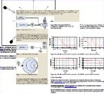
The following article is a brief introduction to and explanation of the theory and application of the named frequency selective devices. A Bias-T is frequency dependent just as much so as a band splitter or diplexer; it differentiates between DC (0 Hz) and the RF frequency. Bree Engineering Corporation was founded in 1999 and is a manufacturer of custom electronic filters, multiplexers, filter banks and other related types of components in the frequency range of 0.1 MHz to 40 GHz. Designs include Chebychev, Bessel, Butterworth, Gaussian, transitional, elliptic-function and pseudo-elliptic-function filters in lumped element, cavity, combline, interdigital ... Measuring Peak and Pulse Power with USB Power Sensors by Orwill Hawkins, LadyBug Technologies As technology and measuring techniques advance, the time eventually comes when continuing to use old methods not only doesn't make sense, but can actually harm your reputation by providing data that cannot be duplicated by customers who long ago adopted the new ways. Orwill Hawkins, of LadyBug Technologies, has written a white paper describing how to make accurate, repeatable peak and pulse power measurements on waveforms using the precision of modern instruments that provide a graphical view of the entity being investigated. USB power meters provide an inexpensive means of obtaining high quality measurements and the benefits of a graphical display environment (on your computer) at a relatively low cost. I particularly like the use of the word 'mesial' in describing the midpoint of a pulse's rising and falling edges. Aeromodeler Dave Wineland Awarded the Nobel Prize in Physics As you might know if you have been an RF Cafe visitor for a while, my life-long hobby has been model aviation. Many notable people have similarly been aeromodelers from a young age, including aircraft designer Burt Rutan, Space Shuttle astronaut Robert "Hoot" Gibson, radio personality Paul Harvey, actor and WWII bomber pilot Jimmy Stewart, Olympiad Bruce Jenner, catamaran and surfboard designer Hobart "Hobie" Alter, to name a few. Physicist Dr. David (Dave) Wineland has just been added to the list since he won the Nobel Prize in Physics in December 2012 for his work on quantum computing. The Academy of Model Aeronautics' (AMA) monthly magazine Model Aviation printed an interview with Dr. Wineland in the January 2013 edition, where he discusses his history with model airplanes and his work at the National Institute of Standards and Technology (NIST) in Boulder, Colorado. Model Model Aviation editor Jay Smith granted permission for me to reprint the article here on RF Cafe since it will likely be of interest to engineers and scientists who visit the website. Reflect Forward Linearizer for Combined Amplifiers by Ray Gutierrez, Micronda LLC This paper is a continuation work for the "New High Efficiency Intermodulation Cancellation Technique for Single Stage Amplifiers." Published in January 2008 on RF Café's Paper section. The paper describes configurations for dual and multiple parallel amplifiers and uses the basic Reflect Forward technique for intermodulation cancellation. Some new improvements were made to the RFAL technique to improve the efficiency and operation. LED Lighting vs. Incandescent Lights for Commercial Buildings Short write-up on benefits of LED lighting. by Kirt Blattenberger, RF Cafe RF Design Magazine Software Contest Winner November 1992 I just ran across this magazine and decided to scan the article. It is a great tutorial on mixer spurious product calculation - if I do say so myself ;-) by Cornell Drentea Here is a short treatise on the history of radar development, beginning in 1793 with Italian scientist Lazarro Spallanzani's experimentation on a bat's use of ultrasound for navigation, on up through modern systems. Efficiency Measurements of Portable-Handset Antennas Using the Wheeler Cap by Darioush Agahi and William Domino In the design of wireless portable devices, antenna efficiency is a variable that can have a great effect on overall system performance, and yet may not always receive the attention it deserves. As an example, RF engineers must frequently make critical tradeoffs in receiver design in order to improve sensitivity by mere fractions of a dB, but a poor antenna efficiency can easily cause a degradation of several dB. This pitfall can occur in systems such as GSM, where many tests are performed using a cable connection to the antenna port; a handset may easily pass such tests, only to be later hampered by its antenna in the field. This paper is targeted at the very important parameter of antenna efficiency, and a measurement technique that can be used to quantify it. Marconi's Legacy: National Sovereignty Claims in Radio by Robert Horvitz Abstract: Presented at the 1st COMMUNIA Workshop on "Technology and the Public Domain," NEXA Center for Internet and Society, Politecnico di Torino, Italy, 18 January 2008. Since early in the 20th century, national governments have asserted sovereignty over the electromagnetic spectrum. These assertions were initially embraced as a way to control the monopolistic ambitions and offensive business practices of the Marconi Wireless Telegraph Company. They are still the basis of radio regulation. However, as wireless communication moves to higher and higher frequencies - into the range of infrared (heat) and free space optics (light) - it is becoming obvious that claiming sovereignty over radio frequencies makes no more sense than claiming sovereignty over colors of the rainbow. Is radio legally different from light? If not, might we someday need government permission to use certain colors of light for certain purposes, as with the invisible colors of radio? GSM Handset Power Amplifier Control Loop Design an Analog Approach by Jason Millard and Darioush Agahi Power amplifier control (PAC) for a Global System for Mobile communications© (GSM©) compatible radio is one of the more challenging aspects of the GSM-based system design. Not only must the radio meet all output radio frequency (RF) spectrum specifications, but the Power Amplifier (PA) control loop must also be stable under varying environmental conditions. This paper starts by looking at the basic control theory, and discusses its advantages over simple open loop control. It then moves on to describe each block of the loop in detail. Stability is also discussed, and then finally, the paper examines a case study radio. New High Efficiency Intermodulation Cancellation Technique for Single Stage Amplifiers by Ray Gutierrez, Micronda LLC
The basic RFAL technique uses the behavior of a transistor when driven into its non-linear operating region. At the high drive level the input reflects not only the fundamental components of the input signal but also the non-linear distortion components appearing at the output of the transistor. The level of the distortion products at the input is sufficiently proportional to the output such that it can be used and processed as a correction or error signal to cancel the output distortion of the transistor amplifier. Block diagrams, schematics, data are included. See follow-on work: Reflect Forward Linearizer for Combined Amplifiers Spectral Leakage in the Discrete Fourier Transform by Greg Adams, with the permission of Lockheed Martin Company, NE&SS SS Math & Physics Seminar
If the test signal is slightly off frequency, i.e. the input signal doesn't complete a whole number of cycles within the DFT time window, a distortion called spectral leakage occurs. A small frequency error has little effect on the main signal, but has a strong effect on the DFT noise floor. The relationship between frequency error, and the signal to noise ratio due to leakage noise has been established. This relationship can be used to determine the frequency resolution which the sine wave generator must have in order to generate a sine wave at a sufficiently accurate frequency. A simple calculator program is provided to evaluate the equations. ADC Toolkit: Used with presentation The Study of Fast Adaptive Algorithms and Introducing New Methods for Increasing the Rate of Convergence and Its Use in Smart Antennas by S.Y. Skandari, Ch. Ghobadi, J. Nourinia, Urmia Univ., Urmia, Iran
by Dr. Nasreddine Benahmed, University of Tlemcen, Algeria A set of accurate closed-forms formulas for the effective dielectric constants of the shielded symmetrical bandline. by Dr. Nasreddine Benahmed, University of Tlemcen, Algeria Design NMR probes using closed-forms formulas of the primary and secondary parameters of the shielded split ring and the shielded symmetrical band resonators . These formulas are based on rigorous analysis by finite element method (FEM) , method of moment (MoM) and curves fitting techniques. In-Building RF Coverage Solutions by Shekar Kulashekaran, shekar.pk@gmail.com This presentation offers a methodical approach to planning and implementing in-building solutions for GSM 900 & 1800 MHz, and CDMA phone systems that helps solve the problem of coverage in offices, garages, shopping centers, etc. Shekar has 6 years of experience planning and installing these systems. Power Amplifier Linearization Using Diode On Voltage by Mrunal A. K. & Makarand Shirasgaonkar - MTech Students, Dr. R. M. Patrikar, Professor, Visvesvaraya National Institute of Technology, Nagpur INDIA.
RF & Microwave Power Amplifier Design 4-Part Lecture Presentation (contains much material from book)
Lecture 1: Nonlinear Active Device Modeling Lecture 2: Impedance Matching Lecture 3: PA Design Fundamentals Lecture 4: High Efficiency Power Amplifier Design Design and Development of Low Noise Amplifier Using 3-dB Quadrature Hybrids by Vandana Kalibhat Ramchandra This paper describes and discusses a procedure of how to design RF/Microwave Low noise amplifier with minimum noise figure and low VSWR. The initial data available is S-parameters of the device. This paper references the RF design tool called ADS by Agilent technology. Short Wire Antennas: A Simplified Approach Part I: Scaling Arguments by Dr. Dan Dobkin veDr. Dan Dobkin version 1.0, enigmatics@batnet.com In this article we shall try to illustrate a simpler and more direct way of understanding how short wire antennas, and by extension other small antennas, interact with traveling electromagnetic waves, in which we focus on the potentials that result directly from charges and currents. Part II will follow if sufficient interest is shown in this first installment. Tutorial of Satellite Communication by Kamran Ahmed, Institute of Information Technology, University of Sindh, Pakistan This is an excellent series of lectures on the basics of satellite communications. ▪ Overview of Satellite Systems ▪ Antennas On the Physical Meaning of the Curl Operator by Christopher K. Horne
- See also: "Pulsed S-parameter Measurements for GSM Amplifiers", MP Digest, June 2004 Using Simulation Tools to Troubleshoot an LC Filter Design by Ed Troy, Aerospace Consulting, LLC Almost everyone uses simulation tools for designing RF, microwave, and high speed digital circuits today. It is essential. But, very few engineers use those same tools for troubleshooting of circuits that are not working correctly. It amazes me that many engineers and technicians still spend days tuning, tweaking, and adjusting RF circuits that do not work properly on the bench. They could probably find, and fix, the problems in much less time by firing up their simulation software. It is much faster to change values, both known and speculated, in a simulation engine than it is to make the same changes on the test bench. by Dr. Alfred I. Grayzel, Dr. Ashok (Ash) K. Gorwara, Paul Kuhn Planar Monolithics Industries, Inc. A method is presented in this paper for realizing tunable amplifiers with bandwidths of less than 0.5%; without the use of superconductors and cryogenic cooling. This method uses a small signal varactor up-converter to achieve these ultra narrow bandwidths. The equivalent circuit for the up-converter is presented as well as the circuit configuration of the narrow band negative resistance amplifier. The design and experimental results are presented for a 0.5% bandwidth negative resistance amplifier at 800 MHz; using this unique circuit design. These devices and circuits can be used for electronic warfare applications such as surveillance, electronic reconnaissance, jamming and frequency hopping. Reflection / Transmission Power Measurements by LadyBug Technologies Obtaining accurate, reliable, and useful measurements of RF power in the forward (transmission) and reverse (reflection) directions requires careful selection of test devices and detection equipment. LadyBug Technologies has produced a white paper describing a method for performing reflection and transmission measurements using a power sensor and a directional coupler. It includes a discussion on coupler directivity and impedance match as a factor in measurement accuracy. Measuring Semiconductor Device Input Parameters with Vector Analysis by Joe Cahak, Sunshine Design Services This article will cover a recent test experience that utilized some thinking about the test fixture, the bias requirements and the device mounting and special calibration offsets needed to de-embed the test fixture response from the device response within the test fixture. The device also had to have bias on several ports simultaneously. We had to establish a "reference plane" within the fixture, from which we can use the Vector Network Analyzer's Port Extension or Phase Offset to dial out the distance from our 1 port calibration reference plane to the point of short reference within the fixture. With this phase offset compensation we can then measure the device capacitance of the part within the fixture and the line length of the test fixture mostly worked out by the port extension. RF Filter and RF SAW Filter for Product Development by John Lai, Oscilent Corporation The purpose of this article is to discuss the important design considerations and development limitations of a Radio Frequency and Surface Acoustic Wave (SAW) Filter (Both IF Filter and RF Filter). Each of the major Electrical Parameters are discussed from a development perspective as follows (reference Figure 1 for further definition): We will also be reviewing RF Filter electrical components. Understanding [Antenna] Polarization by Brian B. Donalson This is a technical paper written to support newly trained satellite operators. It helps in understanding how signals are received from orbiting satellites. Not too technical but if you are someone who wanted to learn a little about satellite communications, this is a good start. Understanding Standard Off-Set vs. Inverted [Satellite] Dishes by Brian B. Donalson This is technical paper written to support newly trained Satellite Operators. It is a paper that shows the difference between a standard off-set satellite dish and an inverted off-set Satellite dish. Technical in nature, but easy to understand. Complete with illustrations to help you understand. A good read even if you know nothing about satellite dishes. A brief overview of the 4G system still in its planning and implementation (and definition) phase, provided by the folks at Broadband Expert. A Graphical Approach to Mixer Spurious Analysis by Kirt Blattenberger, RF Cafe The Spur Web chart rapidly identifies both inband and out-of-band spurs, affording a pictorial view of where conversion system frequencies lie with respect to all spur products. RFDAC (RF Digital-to-Analog Converter) White Paper by Michael Hopkins, CurrentRF
by William Domino, Nooshin Vakilian, and Darioush Agahi In designing today's wireless handset receivers, it is important to maximize both receive sensitivity and resistance to undesired signals, also called "interferers", or "blockers". The starting place for receiver design is the calculation of budgets for noise figure and linearity, usually facilitated by a spreadsheet. While it is straightforward to find the cascaded noise figure (NF) and 1dB compression point (P1dB) using a spreadsheet calculation, it is often not clear how to use these to predict the actual performance of the receiver in the presence of a large blocker. To obtain a reasonably accurate prediction may instead require an inconvenient co-simulation of the system with circuit models embedded. However, a simpler approach is possible, which is still performed at the level of cascade calculations rather than simulation. Expert Witnesses The staff at IMS ExpertServices™ has prepared a few articles on the subject of expert witnesses.
Monolithic Ceramic Block Combline Bandpass Filters by Darioush Agahi, Sykworks Small size and ruggedness are two important factors in the selection of bandpass filters for military and OEM applications. Monolithic ceramic block combline bandpass filters not only offer a size advantage in UHF through L-band frequencies; they also have other characteristics that make them extremely attractive when compared to other technologies. The filters are characteristically lower in cost and have relatively good insertion loss due to their high Q material (Q>10,000). This paper describes the design technique used for ceramic bandpass filters. CAD Oriented Study of Polyimide Interface Layer on Silicon Substrate for RF Applications by Kamaljeet Singh and K Nagachenchaiah Semiconductor Laboratory (SCL), SAS Nagar, Near Chandigarh, India
Coupled Microstrip Filters: Simple Methodologies for Improved Characteristics by Kamaljeet Singh, R. Ramasubramanian, S. Pal Communication Systems Group, ISRO Satellite Center, Bangalore, India This paper presents improved characteristics of the hairpin filter topology. Standard hairpin configuration has the drawback of broader bandwidth, more insertion loss along with poor skirt rate. This paper demonstrates the approach to overcome the limitation inherent in hairpin as well as suppression of the harmonic which is prominent in the microstrip coupled filter topology. Short Wire Antennas: A Simplified Approach by Dr. Dan Dobkin version 1.0 Note: If you get sign-in screens, just close the window and the file will load. Part I: Scaling Arguments How does a wire dipole antenna work? How do we find the resistance and the reactance? Why does the reactance vanish at an appropriate length or frequency? Part II: Detailed Estimates of Scattered Voltage and Current We will now fill in the details of the calculation of scattered current and voltage for a short length of wire with an impinging potential
CHALLENGE "I will offer a $5 Starbucks gift certificate for each algebraic goof reported and corrected." by Kirt Blattenberger, RF Cafe This Excel workbook demonstrates how easy it is to implement a Smith Chart using only a standard x-y scatter chart and coordinate conversions. Load Network Design Techniques for Class E RF and Microwave Amplifier by Andrei Grebennikov, M/A-COM Eurotec The output network of a class E amplifier must provide impedance matching at the fundamental frequency and adequate rejection of harmonic frequencies, while handling DC power to the device. First-Time-Right Design of RF/Microwave Class A Power Amplifiers Using Only S-Parameters by Ivan Boshnakov (ivanb@aerial.co.uk), Senior Principal Engineer, Aerial Facilities Limited (www.aerialfacilities.com) This article describes and discusses a procedure of how to design RF/Microwave Class A power amplifiers in a very efficient and highly accurate manner when the only initial data available are the S-parameters of the transistors. This paper references the "Tandem RF Software Programs Streamline the Design of Power Amplifiers" item by Mr. Boshnakov toward the bottom of this page. by Glen Dash This tutorial series is graciously provided by Dr. Dash: Part 1: An Introduction Part 2: Why Things Radiate Part 3: The Difference a Del Makes Part 4: Equations Even a Computer Can Love Part 5: Radiation From a Small Wire Element Part 6: The Method of Moments These articles provide a magnificently comprehendible presentation of Maxwell's Equations. They originally appeared in Conformity magazine in 1999, and were pulled a couple years ago. All six parts have been revised and condensed into a much small file size to facilitate easier downloads (as of November 15, 2005). Glen Dash is the author of numerous papers on the laws and standards applicable to electronic equipment. He is a graduate of MIT in Electrical Engineering and holds a law degree from Harvard. Please send a note of thanks to Dr. Dash for making these immensely popular articles available. Automatic Telephone Call Indication Device Using Power Line by Manu V Thayyil and Prince V Thachil, Model Engineering College, Thrikkakra, Kochi, India This paper describes the design of an automatic telephone call indication device with power line as the channel for communication via Amplitude Shift Keying. These guys are graduate students and welcome feedback - manuthayyil@yahoo.co.in by Carl Lodstrom Tricks of the trade for successful use of capacitors for decoupling. Criss-Cross RFAL Cancels the IMD Distortion in Amplifiers
The basic RFAL technique uses the behavior of a transistor when driven into its non-linear operating region. At the high drive level the input reflects not only the fundamental components of the input signal but also the non-linear distortion components appearing at the output of the transistor. The level of the distortion products at the input is sufficiently proportional to the output such that it can be used and processed as a correction or error signal to cancel the output distortion of the transistor amplifier. Author: Ray Gutierrez, Micronda LLC. |
|||||||||||||
 |
|||||||||||||
|
|||||||||||||
 Now you don't have to wait for a magazine to
publish your technical article. If you would like to have your article posted here,
please attach it to an e-mail in MS Word format (I will convert it to PDF) or PDF
format, along with a brief description to use with the listing.
Now you don't have to wait for a magazine to
publish your technical article. If you would like to have your article posted here,
please attach it to an e-mail in MS Word format (I will convert it to PDF) or PDF
format, along with a brief description to use with the listing.


|
||||||||||||||||||||||||||||||||||||


