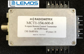
Photo 1 - Radiometrix MCT1-154.600-8 8-Input Remote Control Transmitter
on MURS Band
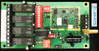
Photo 2 - Radiometrix MCT1-154.600-8 MURS Band Transmitter Circuit
Board
Multi-Use Radio Service (MURS)
By Dan Lemos
Easy Black Box RF Design
Today's IoT way of thinking assumes that everyone is a "programmer." There's
Arduino and MicroPython, which are relatively simple programming languages that
emulate the more complex programming platforms like C, Python and C++. When all
of the programming smoke clears, Arduino can generate most of the same logic patterns
one would scare up with C or C++. The same holds true for MicroPython and its big
brother Python.
Sometimes "programming" is overkill. For instance, what if I show you how to
remotely control a pump or valve with a simple switch? The "switch" can be mechanical
or electronic depending on how much you want to program or how much you want to
solder. If you're interested, read on as I describe how to assemble a long-range
MURS radio link that is capable of controlling large electrical loads that are associated
with electric pumps and valves.
No Previous RF Design Experience Required
As I alluded to earlier, the main radio link will consist of a MURS (Multi-Use
Radio Service) transmitter and a companion receiver. The Multi-Use Radio Service
needs no license and uses channels in the 151 – 154 MHz spectrum range. Our
MURS design will consist of a 1-watt MCT1-154.600 transmitter and a matching MCR1-154.600
receiver.
We really don't care what's inside the MURS transmitter and receiver or how it
works. We only need to know how to feed the transmitter and how to use the resultant
transmission's information on the receiving end. In other words, the MURS radios
are simply "black boxes" that we will incorporate into our overall design.
I've popped off the cover of the MURS transmitter in Photo 1. The receiver is
shown in Photo 2. All you need to know about the units is how to power them, how
to set the DIP switches, how to trigger the transmitter and how to connect to the
receiver's relay contacts.
Powering the receiver and transmitter is simple. Just connect a suitable +12 VDC
power source to the transmitter and receiver power input terminal blocks. Since
we're using a 1-watt transmitter, you'll need to make sure your transmitter power
supply can source enough current to support the transmit current requirements of
the MURS transmitter. You can find the transmitter's current requirement in the
MCT1-154.600 user manual. The receiver will use less current, but you should be
sure your receiver power supply can handle the receiver's maximum current requirement.
Setting the DIP switches is easy. All you need to do is make the transmitter
and receiver 12-position DIP switch positions match. This "matching set" of positions
is the encryption scheme that will be used to establish a logical link between the
transmitter and receiver. In other words, if the DIP switches don't match, the receiver
and transmitter will not talk to each other. The same "make it the same" idea goes
for the 3-position DIP switches and the single-position DIP switches. The smaller
DIP switches determine the frequency that the transmitter and receiver operate on.
Again, if these switches don't match, the transmitter and receiver will never communicate
with each other.
The remaining 4-position DIP switch on the receiver determines if the relays
will operate in continuous mode or on-off mode. Continuous mode operation is defined
as the relay being energized as long as the transmitter signal is received (think
of this like a push-button switch: the bulb is only on if your finger is on the
switch).
On-off mode is akin to switching a light bulb on and off. A signal from the transmitter
trips the "light bulb" (the relay in our case) on and the bulb stays on until a
second signal is received. The second signal turns the light off and the process
is repeated with the reception of the next transmitted signal (just like an ordinary
domestic light switch, that you switch on, or switch off, with a flick of the finger)
Each of the 4 DIP switches corresponds to relay on the receiver. So, we can select
which relays will operate in continuous mode or on-off mode. The mode we choose
to operate in depends upon how we want to control the electrical pump or valve.
Triggering the transmitter is as simple as grounding the selected input pin of
the transmitter's terminal blocks. There are a total of 4 inputs, with each terminal
block supporting 2 inputs and a ground pin. Each transmitter input corresponds to
one of the receiver's relays. Each relay is configured as SPDT. If the pump or valve
we intend to remotely control draws less than 8A, we can control the pump or valve
directly from the receiver's on-board relay. In reality, we really don't want to
tie our receiver directly to a load. An overloaded relay could damage our receiver.
So, we'll use the receiver relays to drive devices that can handle higher voltage
and current loads.
The final requirement for our RF design is to mount the proper antenna on the
transmitter and receiver. We'll need antennae that are tuned to the frequency band
used by our MURS transmitter and receiver. At this point, we can power up our transmitter
and receiver. If we've done everything right so far, absolutely nothing should happen.
Triggering the Transmitter
All we need to do is ground the input terminal associated with the relay
we want to energize on the receiver. These inputs have a (4k7) pull-up resistor
to about +5 V so will work with any "switch".
There are many ways to provide that ground signal. We can use a simple SPST mechanical
switch, an optoisolator, or an open drain/open collector MOSFET or bipolar transistor
output.
A microcontroller (5 V logic level) I/O pin will also work. This all depends
on where your "control" input comes from.
Simplest is the mechanical switch, which only requires some simple "doorbell"
wiring.
The microcontroller I/O pin method requires some soldering and some programming.
An optoisolator is good where your "control" signal is an external voltage, but
where you can't guarantee that voltage will always be 5v, that it will be free of
spikes or overloads, or when it's not referenced to ground
MCT1-154.600-8 Input Circuit Schematics
If your microcontroller I/O pin produces a logic level that isn't compatible
with the +5v logic used in the transmitter then either feed your I/0 pin signal
into the optoisolator (see above) or use a MOSFET or transistor as a buffer. (The
output of a typical optoisolator is an LED-triggered MOSFET or bipolar transistor,
which are integral to the optoisolator. If a microcontroller I/O pin is used, it
simply replaces the optoisolator's internal LED. )
If building up a microcontroller subsystem is beyond your capabilities, you can
use easily obtainable Arduino or MicroPython hardware and software to drive the
input via any of the methods detailed above .
There are multitudes of examples on how to perform this operation using Arduino
or MicroPython on the internet.
Effectively Utilizing the Receiver's Relays
The MURS receiver's relay contacts can switch AC or DC. However, I recommend
not using the receiver relays for heavy or inductive loads. I suggest getting familiar
with the high-power switching devices offered by machine automation companies such
as Automation Direct. You will find that contactors and solid-state relays (SSRs)
may be the buffers you need to drive that pump or valve. If motor control is your
target, you'll need to bone up on servo controllers, which are also listed at Automation
Direct.
Basically, you can find a MURS receiver relay interface to most any pump, valve
or motor at Automation Direct. Why Automation Direct? I have in-depth experience
with their product line. When possible, it's always best to go with things that
have worked for you in the past. When I was working at Kennedy Space Center, we
called that go-with-what-you-know hardware "flight tested hardware".
Flight Testing Your MURS Design
The best way to design with the MURS radio set we've been discussing is to get
the actual hardware and twiddle with it. Toggle the DIP switch settings and observe
the results. Power the remote transmitter and/or receiver with your power source
of choice and observe the results. I use inexpensive +12 VDC power supplies
that can be obtained from Amazon to initially setup and test my MURS designs. If
your MURS design requires remote battery power, take a look at the solar systems
used to power automated gates.
If you are not a programmer and need to control the transmitter via a microcontroller,
get some Arduino or MicroPython hardware and learn the basics. The Arduino and MicroPython
hardware is cheap and the software is free.
The most important thing is not to be shy of trying things out. These units are
robust (if you are sensible: don't connect AC mains to the inputs, leave them out
in the rain or use them as improvised hammers) and should allow any amount of tinkering.
Get out there and test your ideas. If the resulting performance isn't what you
want, try something else. Enjoy yourself.
For more information on the Lemos line of MURS modules please log on to
www.lemosint.com or email
us at
dlemos@lemosint.com.
Best regards, Dan Lemos
Lemos International was founded in 1996. At that time, the wireless industry
was undergoing a period of transition. While many of the wireless industry's efforts
in the early 1990's were geared toward military applications such as radar and avionics,
the demand for nonmilitary wireless technology was growing in the commercial markets
as well. The wireless industry began to see increased consumer interest in wireless
services such as cellular telephone and paging services. Additionally, cutting edge
wireless technology was being implemented in a wide range of established industries
such as automotive, manufacturing, medical, and more. The upswing in the overall
commercial wireless market, coupled with a decline in military spending, meant that
wireless equipment manufacturers were going to require new, specialized component
products to meet their business needs.
P.O. Box 719