Module 12 - Modulation Principles
Pages i,
1-1,
1-11,
1-21,
1-31,
1-41,
1-51,
1-61,
1-71,
2-1,
2-11,
2-21,
2-31,
2-41,
2-51,
2-61,
3-1,
3-11,
3-21,
3-31, AI-1, Index, Assignment 1, 2
Chapter 3
DEMODULATION Learning Objectives
Upon completion of this chapter you will be able to: 1. Describe CW detector circuit
operations for the heterodyne and regenerative detectors. 2. Discuss the requirements for recovery of
intelligence from an AM signal and describe the theory of operation of the following AM demodulators:
series-diode, shunt-diode, common-emitter, and common-base. 3. Describe FM demodulation circuit operation
for the phase-shift and gated-beam discriminators and the ratio-detector demodulator. 4. Describe phase
demodulation circuit operation for the peak, low-pass filter, and conversion detectors.
Introduction In chapters 1 and 2 you studied how to apply intelligence (modulation) to an
RF-carrier wave. Carrier modulation allows the transmission of modulating frequencies without the use of
transmission wire as a medium. However, for the communication process to be completed or to be useful, the
intelligence must be recovered in its original form at the receiving site. The process of re-creating original
modulating frequencies (intelligence) from the RF carrier is referred to as DEMODULATION or DETECTION. Each type
of modulation is different and requires different techniques to recover (demodulate) the intelligence. In this
chapter we will discuss ways of demodulating AM, CW, FM, phase, and pulse modulation. The circuit in which
restoration is achieved is called the DETECTOR or DEModulator (both of these terms are used in NEETS). The term
demodulator is used because the demodulation process is considered to be the opposite of modulation. The output of
an ideal detector must be an exact reproduction of the modulation existing on the RF wave. Failure to
accurately recover this intelligence will result in distortion and degradation of the demodulated signal and
intelligence will be lost. The distortion may be in amplitude, frequency, or phase, depending on the nature of the
demodulator. a nonlinear device is required for demodulation. This nonlinear device is required to recover the
modulating frequencies from the RF envelope. Solid-state detector circuits may be either a PN junction diode or
the input junction of a transistor. In electron-tube circuits, either a diode or the grid or plate circuits of a
triode electron tube may be used as the nonlinear device. Q-1. What is demodulation? Q-2. What is a
demodulator? 3-1
CONTINUOUS-WAVE DEMODULATION Continuous-wave (CW) modulation consists of
on-off keying of a carrier wave. To recover on-off keyed information, we need a method of detecting the presence
or absence of RF oscillations. The CW DEModulator detects the presence of RF oscillations and converts them into a
recognizable form. Figure 3-1 illustrates the received CW in view (A), the rectified CW from a diode detector in
view (B), and the dc output from a filter that can be used to control a relay or light indicator in view (C).

Figure 3-1A. - CW demodulation. RECEIVED CW.

Figure 3-1B. - CW demodulation. RECTIFIED CW FROM DETECTOR.

Figure 3-1C. - CW demodulation. Output FROM FILTER.
Figure 3-2 is a, simplified circuit that could be used as a CW demodulator. The antenna receives the RF
oscillations from the transmitter. The tank circuit, L and C1, acts as a frequency-selective network that is tuned
to the desired RF carrier frequency. The diode rectifies the oscillations and C2 provides filtering to provide a
constant dc output to control the headset. This demodulator circuit is the equivalent of a wire telegraphy circuit
but it has certain disadvantages. For example, if two transmitters are very close in frequency, distinguishing
which transmitting station you are receiving is often impossible without a method of fine tuning the desired
frequency. Also, if the stations are within the frequency bandpass of the input tank circuit, the tank output will
contain a mixture of both signals. Therefore, a method, such as HETERODYNE DETECTION, must be used which provides
more than just the information on the presence or absence of a signal. 3-2
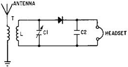
Figure 3-2. - CW demodulator. HETERODYNE DETECTION The use of an AF voltage in the detector aids the operator
in distinguishing between various signals. Since the carrier is unmodulated, the AF voltage can be developed by
using the heterodyne procedure discussed in chapter 1. The procedure is to mix the incoming CW signal with locally
generated oscillations. This provides a convenient difference frequency in the AF range, such as 1,000 hertz. The
AF difference frequency then is rectified and smoothed by a detector. The AF voltage is reproduced by a telephone
headset or a loudspeaker.
Consider the heterodyne reception of the code letter A, as shown in figure 3-3, view (A). The code consists of
a short burst of CW energy (dot) followed by a longer burst (dash). Assume that the frequency of the received CW
signal is 500 kilohertz. The locally generated oscillations are adjusted to a frequency which is higher or lower
than the incoming RF signal (501 kilohertz in this case), as shown in view (B). The voltage resulting from the
heterodyning action between the CW signal [view (A)] and the local oscillator signal [view (B)] is shown in view
(C) as the mixed-frequency signal. ENVELOPE (intelligence) amplitude varies at the BEAT (difference) frequency of
1,000 hertz (501,000 - 500,000). The negative half cycles of the mixed frequency are rectified, as shown in view
(D). The peaks of the positive half cycles follow the 1,000-hertz beat frequency.

Figure 3-3A. - Heterodyne detection. RECEIVED CW Signal. 
Figure 3-3B. - Heterodyne detection. LOCAL Oscillator Signal. 3-3
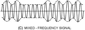
Figure 3-3C. - Heterodyne detection. MIXED-Frequency Signal. 
Figure 3-3D. - Heterodyne detection. RECTIFIED MIXED-Frequency Signal. 
Figure 3-3E. - Heterodyne detection. Audio-BEAT Note FROM FILTER. The CW signal pulsations are removed by the RF filter in the detector output and only the envelope of the
rectified pulses remains. The envelope, shown in view (E), is a 1,000-hertz audio-beat note. This 1,000 hertz,
dot-dash tone may be heard in a speaker or headphone and identified as the letter a by the operator. The
heterodyne method of reception is highly selective and allows little interference from adjacent CW stations. If a
CW signal from a radiotelegraph station is operating at 10,000,000 hertz and at the same time an adjacent station
is operating at 10,000,300 hertz, a simple detector cannot clearly discriminate between the two stations because
the signals are just 300 hertz apart. This is because the bandpass of the tuning circuits is too wide and allows
some of the other signal to interfere. The two carrier frequencies differ by only 0.003 percent and a tuned tank
circuit cannot easily discriminate between them. However, if a heterodyne detector with a local-oscillator
frequency of 10,001,000 hertz is used, then beat notes of 1,000 and 700 hertz are produced by the two signals.
These are audio frequencies, which can be
3-4
distinguished easily by a selective circuit because they differ by 30 percent (compared to the 0.003
percent above). Even if two stations produce identical beat frequencies, they can be separated by
adjusting the local-oscillator or BEAT-Frequency Oscillator (BFO) frequency. For example, if the second station in
the previous example had been operating at 10,002,000 hertz, then both stations would have produced a 1,000-hertz
beat frequency and interference would have occurred. Adjusting the local-oscillator frequency to 9,999,000 hertz
would have caused the desired station at 10,000,000 hertz to produce a 1,000-hertz beat frequency. The other
station, at 10,002,000 hertz, would have produced a beat frequency of 3,000 hertz. Either selective circuits or
the operator can easily distinguish between these widely differing tones. a trained operator can use the variable
local oscillator to distinguish between stations that vary in frequency by only a few hundred hertz. Q-3.
What is the simplest form of CW detector?
Q-4. What are the essential components of a CW receiver system? Q-5. What principle is used to help
distinguish between two CW signals that are close in frequency? Q-6. How does heterodyning distinguish
between CW signals? Regenerative DETECTOR
A simple, one-transistor Regenerative DETECTOR circuit that uses the heterodyning principle for
CW operation is shown in figure 3-4. The circuit can be made to oscillate by increasing the amount of energy fed
back to the tank circuit from the collector-output circuit (by physically moving tickler coil L2 closer to L1
using the regeneration control). This feedback overcomes losses in the base-input circuit and causes
self-oscillations which are controlled by tuning capacitor C1. The received signal from the antenna and the
oscillating frequency are both present at the base of transistor Q1. These two frequencies are heterodyned by the
nonlinearity of the transistor. The resulting beat frequencies are then rectified by the emitter-base junction and
produce a beat note which is amplified in the collector-output circuit. The AF currents in the collector circuit
actuate the phones. The Regenerative DETECTOR (figure 3-4) produces its own oscillations, heterodynes them with an
incoming signal, and rectifies or detects them.
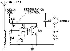
Figure 3-4. - Regenerative detector. 3-5
The regenerative detector is used to receive short-wave code signals because it is easy to adjust and
has high sensitivity and good selectivity. At high frequencies, the amount of signal detuning necessary to produce
an audio-beat note is a small percentage of the signal frequency and causes no trouble. The use of the
regenerative detector for low-frequency code reception, however, is usually avoided. At low frequencies the
detuning required to produce the proper audio-beat frequency is a considerable percentage of the signal frequency.
Although this type detector may be used for AM signals, it has high distortion and is not often used.
Q-7. What simple, one-transistor detector circuit uses the heterodyne principle? Q-8. What three
functions does the transistor in a regenerative detector serve? AM DEMODULATION Amplitude modulation refers to any method of modulating an electromagnetic carrier frequency by varying its
amplitude in accordance with the message intelligence that is to be transmitted. This is accomplished by
heterodyning the intelligence frequency with the carrier frequency. The vector summation of the carrier, sum, and
difference frequencies causes the modulation envelope to vary in amplitude at the intelligence frequency, as
discussed in chapter 1. In this section we will discuss several circuits that can be used to recover this
intelligence from the variations in the modulation envelope. DIODE DETECTORS
The detection of AM signals ordinarily is accomplished by means of a diode rectifier, which may
be either a vacuum tube or a semiconductor diode. The basic detector circuit is shown in its simplest form in view
(A) of figure 3-5. Views (B), (C), and (D) show the circuit waveforms. The demodulator must meet three
requirements: (1) It must be sensitive to the type of modulation applied at the input, (2) it must be nonlinear,
and (3) it must provide filtering. Remember that the AM waveform appears like the diagram of view (B) and the
amplitude variations of the peaks represent the original audio signal, but no modulating signal frequencies exist
in this waveform. The waveform contains only three RF frequencies: (1) the carrier frequency, (2) the sum
frequency, and (3) the difference frequency. The modulating intelligence is contained in the difference between
these frequencies. The vector addition of these frequencies provides the modulation envelope which approximates
the original modulating waveform. It is this modulation envelope that the DIODE DETECTORS use to reproduce the
original modulating frequencies.
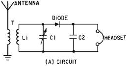
Figure 3-5A. - Series-diode detector and wave shapes. Circuit. 3-6

Figure 3-5B. - Series-diode detector and wave shapes. RF Input Signal.

Figure 3-5C. - Series-diode detector and wave shapes. RECTIFIED Signal. 
Figure 3-5D. - Series-diode detector and wave shapes. Audio Signal. Series-Diode Detector Let's analyze the operation of the circuit shown in
view (A) of figure 3-5. This circuit is the basic type of diode receiver and is known as a Series-DIODE DETECTOR.
The circuit consists of an antenna, a tuned LC tank circuit, a semiconductor diode detector, and a headset which
is bypassed by capacitor C2. The antenna receives the transmitted RF energy and feeds it to the tuned tank
circuit. This tank circuit (L1 and C1) selects which RF signal will be detected. As the tank resonates at the
selected frequency, the wave shape in view (B) is developed across the tank circuit. Because the semiconductor is
a nonlinear device, it conducts in only one direction. This eliminates the negative portion of the RF carrier and
produces the signal shown in view (C). The current in the circuit must be smoothed before the headphones can
reproduce the AF intelligence. This action is achieved by C2 which acts as a filter to 3-7
provide an output that is proportional to the peak RF pulses. The filter offers a low impedance to RF
and a relatively high impedance to AF. (Filters were discussed in NEETS, Module 9, Introduction to Wave-
Generation and Wave-Shaping Circuits.) This action causes C2 to develop the waveform in view (D). This varying AF
voltage is applied to the headset which then reproduces the original modulating frequency. This circuit is called
a series-diode detector (sometimes referred to as a Voltage-DIODE DETECTOR) because the semiconductor diode is in
series with both the input voltage and the load impedance. Voltages in the circuit cause an output voltage to
develop across the load impedance that is proportional to the input voltage peaks of the modulation envelope.
Q-9. What are the three requirements for an AM demodulator? Q-10. What does the simplest diode
detector use to reproduce the modulating frequency? Q-11. What is the function of the diode in a
series-diode detector?
Q-12. In figure 3-5, what is the function of C2? Shunt-Diode Detector The
Shunt-DIODE DETECTOR (figure 3-6) is similar to the series-diode detector except that the output variations are
current pulses rather than voltage pulses. Passing this current through a shunt resistor develops the voltage
output. The input is an RF modulated envelope. On the negative half cycles of the RF, diode CR1 is forward biased
and shunts the signal to ground. On the positive half cycles, current flows from the output through L1 to the
input. a field is built up around L1 that tends to keep the current flowing. This action integrates the RF current
pulses and causes the output to follow the modulation envelope (intelligence) closely. (Integration was discussed
in NEETS, Module 9, Introduction to Wave-Generation and Wave-Shaping Circuits.) Shunt resistor R1 develops the
output voltage from this current flow. Although the shunt detector operates on the principle of current flow, it
is the output voltage across the shunt resistor that is used to reproduce the original modulation signal. The
shunt-diode detector is easily identified by noting that the detector diode is in parallel with both the input and
load impedance. The waveforms associated with this detector are identical to those shown in views (B), (C), and
(D) of figure 3-5.
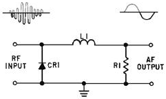
Figure 3-6. - Shunt-diode detector. The series-diode detector is normally used where large input signals are supplied and a linear output is
required. The shunt-diode detector is used where the voltage variations are too small to produce a full output
from audio amplifier stages. Additional current amplifiers are required to bring the output to a usable level.
Other methods of detection and amplification have been developed which will detect low- 3-8
level signals. The next sections will discuss two of these circuits, the common-emitter and
common-base detectors. Q-13. How does the current-diode detector differ from the voltage-diode detector?
Q-14. Under what circuit conditions would the shunt detector be used? Common-Emitter
DETECTOR The Common-Emitter DETECTOR is often used in receivers to supply an amplified detected
output. The schematic for a typical transistor common-emitter detector is shown in figure 3-7. Input transformer
T1 has a tuned primary that acts as a frequency-selective device. L2 inductively couples the input modulation
envelope to the base of transistor Q1. Resistors R1 and R2 are fixed-bias voltage dividers that set the bias
levels for Q1. Resistor R1 is bypassed by C2 to eliminate RF. This RC combination also acts as the load for the
diode detector (emitter-base junction of Q1). The detected audio is in series with the biasing voltage and
controls collector current. The output is developed across R4 which is also bypassed to remove RF by C4. R3 is a
temperature stabilization resistor and C3 bypasses it for both RF and AF.
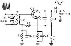
Figure 3-7. - Common-emitter detector. Q1 is biased for slight conduction with no input signal applied. When an input signal appears on the base
of Q1, it is rectified by the emitter-base junction (operating as a diode) and is developed across R1 as a dc bias
voltage with a varying AF component. This voltage controls bias and collector current for Q1. The output is
developed by collector current flow through R4. Any RF ripple in the output is bypassed across the collector load
resistor by capacitor C4. The AF variations are not bypassed. After the modulation envelope is detected in the
base circuit, it is amplified in the output circuit to provide suitable AF output. The output of this circuit is
higher than is possible with a simple detector. Because of the amplification in this circuit, weaker signals can
be detected than with a simple detector. a higher, more usable output is thus developed. Q-15. Which
junction of the transistor in the common-emitter detector detects the modulation envelope? Q-16. Which
component in figure 3-7 develops the AF signal at the input? Q-17. How is the output signal developed in
the common-emitter detector? 3-9
Common-Base DETECTOR Another amplifying detector that is used in portable
receivers is the Common-Base DETECTOR. In this circuit detection occurs in the emitter-base junction and
amplification occurs at the output of the collector junction. The output developed is the equivalent of a diode
detector which is followed by a stage of audio amplification, but with more distortion. Figure 3-8 is a schematic
of a typical common-base detector. Transformer T1 is tuned by capacitor C3 to the frequency of the incoming
modulated envelope. Resistor R1 and capacitor C1 form a self-biasing network which sets the dc operating point of
the emitter junction. The AF output is taken from the collector circuit through audio transformer T2. The primary
of T2 forms the detector output load and is bypassed for RF by capacitor C2.
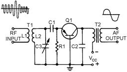
Figure 3-8. - Common-base detector. The input signal is coupled through T1. When capacitor C3 is tuned to the proper frequency, the signal is
passed to the emitter of Q1. When no input signal is present, bias is determined by resistor R1. When the input
signal becomes positive, current flows through the emitter-base junction causing it to be forward biased. C1 and
R1 establish the dc operating point by acting as a filter network. This action provides a varying dc voltage that
follows the peaks of the RF modulated envelope. This action is identical to the diode detector with the
emitter-base junction doing the detecting. The varying dc voltage on the emitter changes the bias on Q1 and causes
collector current to vary in accordance with the detected voltage. Transformer T2 couples these AF current changes
to the output. Thus, Q1 detects the AM wave and then provides amplification for the detected waveform. The
four AM detectors just discussed are not the only types that you will encounter. However, they are representative
of most AM detectors and the same characteristics will be found in all AM detectors. Now let's study some ways of
demodulating frequency-modulated (FM) signals. Q-18. Which junction acts as the detector in a
common-base detector?
Q-19. To what circuit arrangement is a common-base detector equivalent? Q-20. In figure 3-8, which
components act as the filter network in the diode detector? FM DEMODULATION In FM demodulators, the intelligence to be recovered is not in amplitude variations; it is in the variation of the
instantaneous frequency of the carrier, either above or below the center frequency. The 3-10
| - |
Matter, Energy,
and Direct Current |
| - |
Alternating Current and Transformers |
| - |
Circuit Protection, Control, and Measurement |
| - |
Electrical Conductors, Wiring Techniques,
and Schematic Reading |
| - |
Generators and Motors |
| - |
Electronic Emission, Tubes, and Power Supplies |
| - |
Solid-State Devices and Power Supplies |
| - |
Amplifiers |
| - |
Wave-Generation and Wave-Shaping Circuits |
| - |
Wave Propagation, Transmission Lines, and
Antennas |
| - |
Microwave Principles |
| - |
Modulation Principles |
| - |
Introduction to Number Systems and Logic Circuits |
| - |
- Introduction to Microelectronics |
| - |
Principles of Synchros, Servos, and Gyros |
| - |
Introduction to Test Equipment |
| - |
Radio-Frequency Communications Principles |
| - |
Radar Principles |
| - |
The Technician's Handbook, Master Glossary |
| - |
Test Methods and Practices |
| - |
Introduction to Digital Computers |
| - |
Magnetic Recording |
| - |
Introduction to Fiber Optics |
| Note: Navy Electricity and Electronics Training
Series (NEETS) content is U.S. Navy property in the public domain. |
Related Pages on RF Cafe - Amplitude
Modulation - Frequency Modulation -
Quadrature (I/Q) Modulator Sideband Suppression -
Bessel Functions & Graphs -
Modulation Principles, AM Modulation,
NEETS - Modulation Principles,
FM Modulation, NEETS - Modulation
Principles, Demodulation, NEETS - Frequency Mixer, Converter, Multiplier,
Modulator Vendors
|


