Module 12 - Modulation Principles
Pages i,
1-1,
1-11,
1-21,
1-31,
1-41,
1-51,
1-61,
1-71,
2-1,
2-11,
2-21,
2-31,
2-41,
2-51,
2-61,
3-1,
3-11,
3-21,
3-31, AI-1, Index, Assignment 1, 2
When greater
frequency stability is required, the oscillator should not be keyed, but should remain in continuous operation;
other transmitter circuits may be keyed. This procedure keeps the oscillator tube at a normal operating
temperature and offers less chance for frequency variations to occur each time the key is closed.
KEYING RELAYS. - In transmitters using a crystal-controlled oscillator, the keying is almost always in a
circuit stage following the oscillator. In large transmitters (75 watts or higher), the ordinary hand key cannot
accommodate the plate current without excessive arcing. Warning BECAUSE of The
High PLATE POTENTIALS useD, OPERATING a Hand KEY IN The PLATE Circuit Is DANGEROUS. a SLIGHT SLIP of The Hand
BELow The KEY KNOB COULD RESULT IN SEVERE SHOCK OR, IN The CASE of DEFECTIVE RF PLATE CHOKES, a SEVERE RF BURN. In larger transmitters, some local low-voltage supply, such as a battery, is used with the hand key to open and
close a circuit through the coils of a KEYING RELAY. The relay contacts open and close the keying circuit of the
amplifier. a schematic diagram of a typical relay-operated keying system is shown in figure 1-25. The hand key
closes the circuit from the low-voltage supply through the coil (L) of the keying relay. The relay armature closes
the relay contacts as a result of the magnetic pull exerted on the armature. The armature moves against the
tension of a spring. When the hand key is opened, the relay coil is deenergized and the spring opens the relay
contacts. 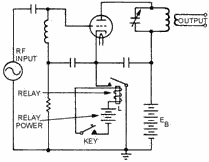
Figure 1-25. - Relay-operated keying system. KEY CLICKS. - Ideally, CW keying a transmitter should instantly start and stop
radiation of the carrier completely. However, the sudden application and removal of power causes rapid surges of
current which may cause interference in nearby receivers. Even though such receivers are tuned to frequencies far
removed from that of the transmitter, interference may be present in the form of "clicks" or "thumps." KEY-CLICK
FILTERS are used in the keying systems of radio transmitters to prevent such interference. Two types of key-click
filters are shown in figure 1-26. 1-31
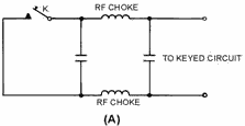
Figure 1-26A. - Key-click filters. 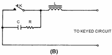
Figure 1-26B. - Key-click filters. The capacitors and RF chokes in figure 1-26, views (A) and (B), prevent surges of current. In view
(B), the choke coil causes a lag in the current when the key is closed, and the current builds up gradually
instead of instantly. The capacitor charges as the key is opened and slowly releases the energy stored in the
magnetic field of the inductor. The resistor controls the rate of charge of the capacitor and also prevents
sparking at the key contacts by the sudden discharge of the capacitor when the key is closed.
MACHINE KEYING. - The speed with which information can be transmitted using a hand key depends on the
keying ability of the operator. Early communicators turned to mechanized methods of keying the transmitters to
speed transmissions. More information could be passed in a given time by replacing the hand-operated key with a
keying device capable of reading information from punched tape. Using this method, several operators could prepare
tapes at their normal operating speed. The tapes could then be read through the keying device at a higher rate of
speed and more information could be transmitted in a given amount of time. Spectrum Analysis Continuous-wave transmission has the disadvantage of being a relatively slow transmission method. Still, it has
several advantages. Some of the advantages of CW transmission are a high degree of clarity under severe noise
conditions, long-range operation, and narrow bandwidth. a highly skilled operator can pick out and read a CW
signal even though it has a high degree of background noise or interference. Since only a single-carrier frequency
is being transmitted, all of the transmitter power can be concentrated in the intelligence. This concentration of
power gives the transmission a greater range. The use of spectrum 1-32
analysis (figure 1-27) illustrates the transmitted frequency characteristics of a CW signal. Because
the CW signal is a pure sine wave, it occupies only a single frequency in the RF spectrum and the system is
relatively simple.
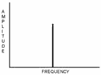
Figure 1-27. - Carrier-wave signal spectrum analysis. Q-18. What is amplitude modulation? Q-19. What are the three requirements for CW
transmission? Q-20. Name two methods of oscillator keying. Q-21. State the
method used to increase the speed of keying in a CW transmitter. Q-22. Name three advantages of
CW transmission. Single-Stage Transmitters A simple, single-tube CW transmitter can be made by
coupling the output of an oscillator directly to an antenna (figure 1-28). The primary purpose of the oscillator
is to develop an RF voltage which has a constant frequency and is immune to outside factors which may cause its
frequency to shift. The output of this simple transmitter is controlled by placing a telegraph key at point K in
series with the voltage
supply. Since the plate supply is interrupted when the key is open, the circuit oscillates only as long as the key
is closed. Although the transmitter shown uses a Colpitts oscillator, any of the oscillators previously described
in NEETS, Module 9, Introduction to Wave-Generation and Wave-Shaping Circuits can be used.
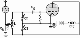
Figure 1-28. - Simple electron-tube transmitter. 1-33
Capacitors C2 and C3 can be GANGED (mechanically linked together) to simplify tuning. Capacitor C1 is used to tune (resonate) the antenna to the transmitter frequency. CA is the effective capacitance existing between
the antenna and ground. This antenna-to-ground capacitance is in parallel with the tuning capacitors, C2 and
C3. Since the antenna has capacitance, any change in its length or position, such as that caused by swaying of the
antenna, changes the value of CA and causes the oscillator to change frequency. Because these frequency changes
are undesirable for reliable communications, the multistage transmitter was developed to increase reliability.
Multistage Transmitters The simple, single-tube transmitter, shown in figure 1-28, is rarely used
in practical equipment. Most of the transmitters you will see use a number of tubes or stages. The number used
depends on the frequency, power, and application of the equipment. For your study, the following three categories
of CW transmitters are discussed: (1) master oscillator power amplifier (MOPA) transmitters, (2) multistage,
high-power transmitters, (3) high- and very-high frequency transmitters. The MOPA is both an oscillator
and a power amplifier. Power-amplifying stages and frequency- multiplying stages must be used to increase power
and raise the frequency from those achievable in a MOPA. The main difference between many low- and high-power
transmitters is in the number of power- amplifying stages that are used. Similarly, the main difference between
many high- and very-high frequency transmitters is in the number of frequency-multiplying stages used.
MASTER Oscillator Power Amplifier. - For a transmitter to be stable, its oscillator must not be LoadED
DOWN. This means that its antenna (which can present a varying impedance) must not be connected directly to the
oscillator circuit. The RF oscillations must be sent through another circuit before they are fed to the antenna
for good frequency stability to be obtained. That additional circuit is an RF power amplifier. Its purpose is to
raise the amplitude of RF oscillations to the required output power level and isolate the oscillator from the
antenna. Any transmitter consisting of an oscillator and a single-amplifier stage is called a master oscillator
power amplifier transmitter (MOPA), as shown in figure 1-29.

Figure 1-29. - Block diagram of a master oscillator power amplifier transmitter (MOPA). Most MOPA transmitters have only one tube amplifier in the power-amplifier stage. However, the
oscillator may not produce sufficient power to drive a power-amplifier tube to the power output level required for
the antenna. In such cases, the power-amplifier stages are designed to use two or more amplifiers which can be
driven by the oscillator. Two or more amplifiers can be connected in parallel (with similar elements of each tube
connected) or in a push-pull arrangement. In a push-pull amplifier, the grids are fed equal RF voltages that are
180 degrees out of phase. The main advantage of a MOPA transmitter is that the power-amplifier stage isolates the oscillator from the
antenna. This prevents changes in antenna-to-ground capacitance from affecting the oscillator 1-34
frequency. a second advantage is that the RF power amplifier is operated so that a small change in the
voltage applied to its grid circuit will produce a large change in the power developed in its plate circuit. RF power amplifiers require that a specific amount of power be fed into the grid circuit. Only in this way can
the tube deliver an amplified power output. However, the stable oscillator can produce only limited amounts of
power. Therefore, the MOPA transmitter is limited in the amount of power it can develop. This is one of the
disadvantages of the MOPA transmitter. Another disadvantage is that it often is impractical for use at very- and
ultra-high frequencies. The reason is that the stability of self-excited oscillators decreases rapidly as the
operating frequency increases. Circuit tuning capacitances are small at high frequencies and stray capacitances
adversely affect frequency stability.
MULTIsTAGE High-Power Transmitters. - The power amplifier of a high-power transmitter may
require far more driving power than can be supplied by an oscillator. Therefore, one or more low-power
intermediate amplifiers may be inserted between the oscillator and the final power amplifier to boost power to the
antenna. In some types of equipment, a Voltage Amplifier, called a BUFFER is used between the oscillator and the
first intermediate amplifier. The ideal buffer is operated class a and is biased negatively to prevent grid
current flow during the excitation cycle. Therefore, it does not require driving power from, nor does it load
down, the oscillator. The purpose of the buffer is to isolate the oscillator from the following stages and to
minimize changes in oscillator frequency that occur with changes in loading. a buffer is required when keying
takes place in an intermediate or final amplifier operating at comparatively high power. Look at the block
diagrams of several medium-frequency transmitters in figure 1-30. The input and output powers are given for each
stage. You should be able to see that the power output rating of a transmitter can be increased by adding
amplifier tubes capable of delivering the power required.
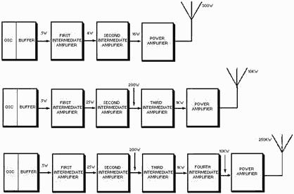
Figure 1-30. - Block diagram of several medium-frequency transmitters. 1-35
HF and VHF Transmitters. - Oscillators are too unstable for direct frequency control in
very- and ultra-high frequency transmitters. Therefore, these transmitters have oscillators operating at
comparatively low frequencies, sometimes as low as 1/100 of the output frequency. The oscillator frequency is
raised to the required output frequency by passing it through one or more Frequency MULTIPLIERS. Frequency
multipliers are special RF power amplifiers which multiply the input frequency. In practice, the MULTIPLICATION
FACTOR (number of times the input frequency is multiplied) is seldom larger than five in any one stage. The block
diagram of a typical VHF transmitter, designed for continuous tuning between 256 and 288 megahertz, is shown in
figure 1-31.
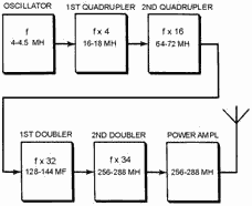
Figure 1-31. - Block diagram of a vhf transmitter. The stages which multiply the frequency by two are DOUBLERS; those which multiply by four are
QUADRUPLERS. The oscillator is tunable from 4 to 4.5 megahertz. The multiplier stages increase the frequency by
multiplying successively by 4, 4, 2, and 2, for a total factor of 64. In high-power, high- frequency transmitters,
one or more intermediate amplifiers may be used between the last frequency multiplier and the power amplifier. Q-23. Name a disadvantage of a single-stage CW transmitter. Q-24. What is the purpose of
the power-amplifier stage in a master oscillator power amplifier CW transmitter? Q-25. What
is the purpose of frequency-multiplier stages in a VHF transmitter? Amplitude
MODULATION
The telegraph and radiotelegraph improved man's ability to communicate by allowing speedy passage
of information between two distant points. However, it failed to satisfy one of man's other communications needs;
that is, the ability to hear and be heard, by voice, at a great distance. In an effort to improve on the
telegraph, Alexander Graham Bell developed the principles on which modern communications are built. He
developed the modulation of an electric current by complex waveforms, the demodulation of the resulting wave, and
recovery of the original waveform. This section will examine the process of varying an electric current in
amplitude at an audio frequency.
1-36
Microphones If an RF carrier is to convey intelligence, some feature of the
carrier must be varied in accordance with the information to be transmitted. In the case of speech
intelligence, sound waves must be converted to electrical energy. A MICROPHONE is an
energy converter that changes sound energy into electrical energy. a diaphragm in the microphone moves in and out
in accordance with the compression and rarefaction of the atmosphere caused by sound waves. The diaphragm is
connected to a device that causes current flow in proportion to the instantaneous pressure delivered to it. Many
devices can perform this function. The particular device used in a given application depends on the
characteristics desired, such as sensitivity, frequency response, impedance matching, power requirements, and
ruggedness. The SENSITIVITY or Efficiency
of a microphone is usually expressed in terms of the electrical power level which the microphone delivers
to a matched-impedance load compared to the sound level being converted. The sensitivity is rated in dB and must
be as high as possible. a high microphone output requires less gain in the amplifiers used with the microphone.
This keeps the effects of thermal noise, amplifier hum, and noise pickup at a minimum. For good quality
sound reproduction, the electrical signal from the microphone must correspond in frequency content to the original
sound waves. The microphone response should be uniform, or flat, within its frequency range and free from the
electrical or mechanical generation of new frequencies. The impedance of a microphone is important in that
it must be matched to the microphone cable and to the amplifier input as well as to the amplifier input load.
Exact impedance matching is not always possible, especially in the case where the impedance of the microphone
increases with an increase in frequency. a long microphone cable tends to seriously attenuate the high frequencies
if the microphone impedance is high. This attenuation is caused by the increased capacitive action of the line at
higher frequencies. If the microphone has a low impedance, a lower voltage is developed in the microphone, and
more voltage is available at the load. Because many microphone lines used aboard ship are long, low- impedance
microphones must be used to preserve a sufficiently high voltage level- over the required frequency range. The symbol used to represent a microphone in a schematic diagram is shown in figure 1-32. The schematic symbol
identifies neither the type of microphone used nor its characteristics.

Figure 1-32. - Microphone schematic symbol. CARBON MICROPHONE. - Operation of the Single-BUTTON CARBON MICROPHONE figure 1-33,
view (A) is based on varying the resistance of a pile of carbon granules located within the microphone. An
insulated cup, referred to as the button, holds the loosely piled granules. It is so mounted that it is in
constant contact with the thin metal diaphragm. Sound waves striking the diaphragm vary the pressure on the button
which varies the pressure on the pile of carbon granules. The dc resistance of the carbon granule pile is varied
by this pressure. This varying resistance is in series with a battery and the 1-37
primary of a transformer. The changing resistance of the carbon pile produces a corresponding change
in the current of the circuit. The varying current in the transformer primary produces an alternating voltage in
the secondary. The transformer steps up the voltage and matches the low impedance of the microphone to the high
impedance of the first amplifier. The voltage across the secondary may be as high as 25 volts peak. The impedance
of this type of microphone varies from 50 to 200 ohms. This effect is caused by the pressure of compression and
rarefaction of sound waves, discussed in chapter 1 of NEETS, Module 10, Introduction to Wave Propagation,
Transmission Lines, and Antennas.
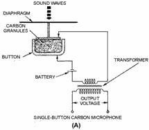
Figure 1-33A. - Carbon microphones. Single-BUTTON CARBON MICROPHONE. The DOUBLE-BUTTON CARBON MICROPHONE is shown in figure 1-33, view (B). Here, one
button is positioned on each side of the diaphragm so that an increase in resistance on one side is accompanied by
a simultaneous decrease in resistance on the other. Each button is in series with the battery and one-half of the
transformer primary. The decreasing current in one-half of the primary and the increasing current in the other
half produces an output voltage in the secondary winding. The output voltage is proportional to the sum of the
primary winding signal components. This action is similar to that of push-pull amplifiers.
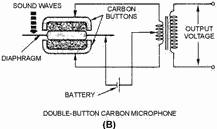
Figure 1-33B. - Carbon microphones. DOUBLE-BUTTON CARBON MICROPHONE. 1-38
One disadvantage of carbon microphones is that of a constant BACKGround HIsS (hissing noise) which
results from random changes in the resistance between individual carbon granules. Other disadvantages are reduced
sensitivity and distortion that may result from the granules packing or sticking together. The carbon microphone
also has a limited frequency response. Still another disadvantage is a requirement for an external voltage source. The disadvantages, however, are offset by advantages that make its use in military applications widespread. It is
lightweight, rugged, and can produce an extremely high output. Crystal MICROPHONE. - The
Crystal MICROPHONE uses the PIEZOELECTRIC EFFECT of Rochelle salt, quartz, or other crystalline materials. This
means that when mechanical stress is placed upon the material, a voltage electromagnetic force (EMF) is generated.
Since Rochelle salt has the largest voltage output for a given mechanical stress, it is the most commonly used
crystal in microphones. View (A) of figure 1-34 is a crystal microphone in which the crystal is mounted so that
the sound waves strike it directly. View (B) has a diaphragm that is mechanically linked to the crystal so that
the sound waves are indirectly coupled to the crystal.
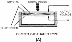
Figure 1-34A. - Crystal microphones. 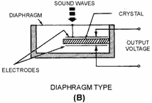
Figure 1-34B. - Crystal microphones. 1-39
A crystal microphone has a high impedance and does not require an external voltage source. It can be
connected directly into the input circuit of a high-gain amplifier. However, because its output is low, several
stages of high-gain amplification are required. Crystal microphones are delicate and must be handled with care.
Exposure to temperatures above 52 degrees Celsius (125 degrees Fahrenheit) may permanently damage the crystal
unit. Crystals are also soluble in water and other liquids and must be protected from moisture and excessive
humidity. DYNAMIC MICROPHONE. - a cross section of the DYNAMIC or MOVING-COIL MICROPHONE is
shown in figure 1-35. a coil of fine wire is mounted on the back of the diaphragm and located in the magnetic
field of a permanent magnet. When sound waves strike the diaphragm, the coil moves back and forth cutting the
magnetic lines of force. This induces a voltage into the coil that is an electrical reproduction of the sound
waves. 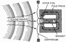
Figure 1-35. - Dynamic microphone. The sensitivity of the dynamic microphone is almost as high as that of the carbon type. It is
lightweight and requires no external voltage. The dynamic microphone is rugged and can withstand the effects of
vibration, temperature, and moisture. This microphone has a uniform response over a frequency range that extends
from 40 to 15,000 hertz. The impedance is very low (generally 50 ohms or less). a transformer is required to match
its impedance to that of the input of an af amplifier. Magnetic MICROPHONE. - The Magnetic
or MOVING-ARMATURE MICROPHONE (figure 1-36) consists of a coil wound on an armature that is mechanically connected
to the diaphragm with a driver rod. The coil is located between the pole pieces of the permanent magnet. Any
vibration of the diaphragm vibrates the armature at the same rate. This varies the magnetic flux in the armature
and through the coil. 1-40
| - |
Matter, Energy,
and Direct Current |
| - |
Alternating Current and Transformers |
| - |
Circuit Protection, Control, and Measurement |
| - |
Electrical Conductors, Wiring Techniques,
and Schematic Reading |
| - |
Generators and Motors |
| - |
Electronic Emission, Tubes, and Power Supplies |
| - |
Solid-State Devices and Power Supplies |
| - |
Amplifiers |
| - |
Wave-Generation and Wave-Shaping Circuits |
| - |
Wave Propagation, Transmission Lines, and
Antennas |
| - |
Microwave Principles |
| - |
Modulation Principles |
| - |
Introduction to Number Systems and Logic Circuits |
| - |
- Introduction to Microelectronics |
| - |
Principles of Synchros, Servos, and Gyros |
| - |
Introduction to Test Equipment |
| - |
Radio-Frequency Communications Principles |
| - |
Radar Principles |
| - |
The Technician's Handbook, Master Glossary |
| - |
Test Methods and Practices |
| - |
Introduction to Digital Computers |
| - |
Magnetic Recording |
| - |
Introduction to Fiber Optics |
| Note: Navy Electricity and Electronics Training
Series (NEETS) content is U.S. Navy property in the public domain. |
|


