|
[Go to TOC]
RS-485 INTERFACE
STANDARD FOR ELECTRICAL CHARACTERISTICS OF GENERATORS AND RECEIVERS FOR USE IN BALANCED DIGITAL MULTIPOINT SYSTEMS
Introduction: The RS-485 is the recommend standard by the Electronic Industries Association (EIA) that specifies
the electrical characteristics of generators and receivers that may be employed for the interchange of binary signals in multipoint interconnection
of digital equipments. When implemented within the guidelines, multiple generators and receivers may be attached to a common interconnecting
cable. An interchange system includes one or more generators connected by a balanced interconnecting cable to one or more receivers and terminating
resistors. 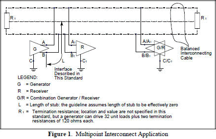 Electrical Characteristics: The electrical characteristics that are specified
are measured at an interconnect point supplied by the devices manufacturer. Figure 1 shows an interconnection application of generators and
receivers having the electrical parameters specified. The elements in the application are: generators, receivers, transmission cables, and termination
resistances (Rt). The loads on the system caused by each receiver and passive generator shall be defined in terms of unit loads. Each generator
can drive up to 32 unit loads consisting of both receivers and generators in the passive state. The loading caused by receivers and passive
generators on the interconnect must be considered in defining the device electrical characteristics. Two areas are of concern: the DC load and
the AC load characteristics. The DC load is defined as a number or fractions of "unit loads". The AC loading is not standardized but must be
considered in the design of a system using the devices meeting this standard. Electrical Characteristics: The electrical characteristics that are specified
are measured at an interconnect point supplied by the devices manufacturer. Figure 1 shows an interconnection application of generators and
receivers having the electrical parameters specified. The elements in the application are: generators, receivers, transmission cables, and termination
resistances (Rt). The loads on the system caused by each receiver and passive generator shall be defined in terms of unit loads. Each generator
can drive up to 32 unit loads consisting of both receivers and generators in the passive state. The loading caused by receivers and passive
generators on the interconnect must be considered in defining the device electrical characteristics. Two areas are of concern: the DC load and
the AC load characteristics. The DC load is defined as a number or fractions of "unit loads". The AC loading is not standardized but must be
considered in the design of a system using the devices meeting this standard.
General System Configuration:
The generators and receivers conforming to the RS-485 standard can operate with a common mode voltage between -7 volts and +7 volts ( instantaneous
). The common mode voltage is defined to be any uncompensated combination of generator-receiver ground potential difference and longitudinally
coupled peak noise voltage measured between the receiver circuit ground and cable with the generator ends of the cable short circuited to ground,
plus the generator offset voltage (Vos). Grounding Arrangements: Proper operation of the generator and receiver
circuits requires the presence of a signal return path between the circuit grounds of the equipment at each end of the interconnection. The
grounding arrangements are shown in Figure 2. Where the circuit reference is provided by a third conductor, the connection between circuit common
and the third conductor must contain some resistance ( e.g., 100 ohms ) to limit circulating currents when other ground connections are provided
for safety. Some applications may require the use of shielded interconnecting cable for EMI or other purposes. The shield shall be connected
to frame ground at either or both ends, depending on the application.
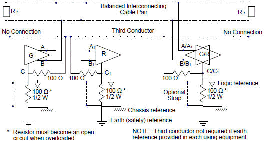
Figure 2. Grounding Arrangements
Similarity with RS-422-A: In certain instances, it may be possible to produce generators and receivers that meet the requirements
of both RS-422-A and of RS-485. Table 1 depicts the differences in parameter specifications which exist between the two documents.
Table 1. Comparison of RS-422-A and RS-485 Characteristics
|
Min. output voltage |
2V into 100 ohm > 1/2 open circuit V |
1.5 V into 54 ohms |
|
Ishort to ground |
150 mA maximum |
|
|
Ishort to -7, +12 volts |
|
250 mA peak |
|
trise time |
< 0.1 tb , 100 ohm load |
< 0.3 tb , 54 ohm, 50 pF load |
Where tb = time duration of the unit interval at the applicable data signaling rate (pulse width
Table of Contents for Electronics Warfare and Radar Engineering Handbook
Introduction |
Abbreviations | Decibel | Duty
Cycle | Doppler Shift | Radar Horizon / Line
of Sight | Propagation Time / Resolution | Modulation
| Transforms / Wavelets | Antenna Introduction
/ Basics | Polarization | Radiation Patterns |
Frequency / Phase Effects of Antennas |
Antenna Near Field | Radiation Hazards |
Power Density | One-Way Radar Equation / RF Propagation
| Two-Way Radar Equation (Monostatic) |
Alternate Two-Way Radar Equation |
Two-Way Radar Equation (Bistatic) |
Jamming to Signal (J/S) Ratio - Constant Power [Saturated] Jamming
| Support Jamming | Radar Cross Section (RCS) |
Emission Control (EMCON) | RF Atmospheric
Absorption / Ducting | Receiver Sensitivity / Noise |
Receiver Types and Characteristics |
General Radar Display Types |
IFF - Identification - Friend or Foe | Receiver
Tests | Signal Sorting Methods and Direction Finding |
Voltage Standing Wave Ratio (VSWR) / Reflection Coefficient / Return
Loss / Mismatch Loss | Microwave Coaxial Connectors |
Power Dividers/Combiner and Directional Couplers |
Attenuators / Filters / DC Blocks |
Terminations / Dummy Loads | Circulators
and Diplexers | Mixers and Frequency Discriminators |
Detectors | Microwave Measurements |
Microwave Waveguides and Coaxial Cable |
Electro-Optics | Laser Safety |
Mach Number and Airspeed vs. Altitude Mach Number |
EMP/ Aircraft Dimensions | Data Busses | RS-232 Interface
| RS-422 Balanced Voltage Interface | RS-485 Interface |
IEEE-488 Interface Bus (HP-IB/GP-IB) | MIL-STD-1553 &
1773 Data Bus | This HTML version may be printed but not reproduced on websites.
|


