Electronic Warfare and Radar Systems Engineering Handbook |
|
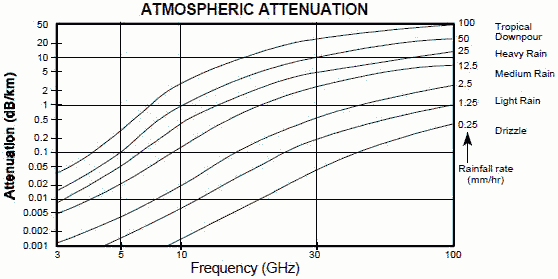
RF ATMOSPHERIC ABSORPTION / DUCTING Signal losses are associated with each stage of signal processing in both the transmitting and receiving portions of the system. The transmitting losses include power transmission efficiency, waveguide and antenna losses, and duplexer losses. In the receiver, losses include antenna, waveguide, RF amplifier, mixer, and IF amplifier. In addition to these losses, energy traveling through the atmosphere suffers from atmospheric attenuation caused primarily by absorption by the gasses. For lower frequencies (below 10 GHz), the attenuation is reasonably predictable. For high frequencies in the millimeter wave range, the attenuation not only increases, but becomes more dependent upon peculiar absorbing characteristics of H2O, O2, and the like. Figure 1 shows the areas of peak absorption in the millimeter wave spectrum. Figure 2 shows how the intensity of precipitation can affect atmospheric attenuation.
Figure 1. Atmospheric Absorption of Millimeter Waves
Figure 2. Atmospheric Attenuation
Figure 3. Ducting Ducting is an increase in range that an electromagnetic wave will travel due to a temperature inversion of the lower atmosphere (troposphere) as shown in Figure 3. The temperature inversion forms a channel or waveguide (duct) for the waves to travel in, and they can be trapped, not attenuating as would be expected from the radar equation. Ducting may also extend range beyond what might be expected from limitations of the radar horizon (see Section 2-9).
The ducting phenomena is frequency sensitive. The thicker the duct, the lower the minimum trapped frequency.
A similar occurrence takes place with ionospheric refraction, however the greatest increase in range occurs in the lower frequencies. This is familiar to amateur radio operators who are able to contact counterparts “around the world”.
Table of Contents for Electronics Warfare and Radar Engineering Handbook Introduction | Abbreviations | Decibel | Duty Cycle | Doppler Shift | Radar Horizon / Line of Sight | Propagation Time / Resolution | Modulation | Transforms / Wavelets | Antenna Introduction / Basics | Polarization | Radiation Patterns | Frequency / Phase Effects of Antennas | Antenna Near Field | Radiation Hazards | Power Density | One-Way Radar Equation / RF Propagation | Two-Way Radar Equation (Monostatic) | Alternate Two-Way Radar Equation | Two-Way Radar Equation (Bistatic) | Jamming to Signal (J/S) Ratio - Constant Power [Saturated] Jamming | Support Jamming | Radar Cross Section (RCS) | Emission Control (EMCON) | RF Atmospheric Absorption / Ducting | Receiver Sensitivity / Noise | Receiver Types and Characteristics | General Radar Display Types | IFF - Identification - Friend or Foe | Receiver Tests | Signal Sorting Methods and Direction Finding | Voltage Standing Wave Ratio (VSWR) / Reflection Coefficient / Return Loss / Mismatch Loss | Microwave Coaxial Connectors | Power Dividers/Combiner and Directional Couplers | Attenuators / Filters / DC Blocks | Terminations / Dummy Loads | Circulators and Diplexers | Mixers and Frequency Discriminators | Detectors | Microwave Measurements | Microwave Waveguides and Coaxial Cable | Electro-Optics | Laser Safety | Mach Number and Airspeed vs. Altitude Mach Number | EMP/ Aircraft Dimensions | Data Busses | RS-232 Interface | RS-422 Balanced Voltage Interface | RS-485 Interface | IEEE-488 Interface Bus (HP-IB/GP-IB) | MIL-STD-1553 & 1773 Data Bus | This HTML version may be printed but not reproduced on websites. |


