Electronic Warfare and Radar Systems Engineering Handbook |
|
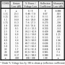
VOLTAGE STANDING WAVE RATIO (VSWR) / REFLECTION COEFFICIENT RETURN LOSS / MISMATCH LOSS When a transmission line is terminated with an impedance, ZL, that is not equal to the characteristic impedance of the transmission line, ZO, not all of the incident power is absorbed by the termination. Part of the power is reflected back so that phase addition and subtraction of the incident and reflected waves creates a voltage standing wave pattern on the transmission line. The ratio of the maximum to minimum voltage is known as the Voltage Standing Wave Ratio (VSWR) and successive maxima and minima are spaced by 180° (λ/2).
The reflection coefficient, ρ, is defined as Er/Ei and in general, the termination is complex in value, so that ρ will be a complex number.
Additionally we define:
If the equation for VSWR is solved for the reflection coefficient, it is found that:
The return loss is related through the following equations:
Return loss is a measure in dB of the ratio of power in the incident wave to that in the reflected wave, and as defined above always has a positive value. For example if a load has a Return Loss of 10 dB, then 1/10 of the incident power is reflected. The higher the return loss, the less power is actually lost. Also of considerable interest is the Mismatch Loss. This is a measure of how much the transmitted power is attenuated due to reflection. It is given by the following equation: Mismatch Loss = -10 log (1 - ρ2) For example, an antenna with a VSWR of 2:1 would have a reflection coefficient of 0.333, a mismatch loss of 0.51 dB, and a return loss of 9.54 dB (11% of your transmitter power is reflected back). In some systems this is not a trivial amount and points to the need for components with low VSWR. If 1000 watts (60 dBm/30 dBW) is applied to this antenna, the return loss would be 9.54 dB. Therefore, 111.1 watts would be reflected and 888.9 watts (59.488 dBm/29.488 dBW) would be transmitted, so the mismatch loss would be 0.512 dB.
Transmission line attenuation improves the VSWR of a load or antenna. For example, a transmitting antenna with a VSWR of 10:1 (poor) and a line loss of 6 dB would measure 1.5:1 (okay) if measured at the transmitter. Figure 1 shows this effect. Therefore, if you are interested in determining the performance of antennas, the VSWR should always be measured at the antenna connector itself rather than at the output of the transmitter. Transmit cabling will load the line and create an illusion of having a better antenna VSWR. Transmission lines should have their insertion loss (attenuation) measured in lieu of VSWR, but VSWR measurements of transmission lines are still important because connection problems usually show up as VSWR spikes. Historically VSWR was measured by probing the transmission line. From the ratio of the maximum to minimum voltage, the reflection coefficient and terminating impedance could be calculated. This was a time consuming process since the measurement was at a single frequency and mechanical adjustments had to be made to minimize coupling into circuits. Problems with detector characteristics also made the process less accurate. The modern network analyzer system sweeps very large frequency bandwidths and measures the incident power, Pi, and the reflected power, Pr . Because of the considerable computing power in the network analyzer, the return loss is calculated from the equation given previously, and displayed in real time. Optionally, the VSWR can also be calculated from the return loss and displayed real time. If a filter is needed on the output of a jammer, it is desirable to place it approximately half way between the jammer and antenna. This may allow the use of a less expensive filter, or a reflective filter vs an absorptive filter. Special cases exist when comparing open and shorted circuits. These two conditions result in the same ∞ VSWR and zero dB return loss even though there is a 180° phase difference between the reflection coefficients. These two conditions are used to calibrate a network analyzer.
Table of Contents for Electronics Warfare and Radar Engineering Handbook Introduction | Abbreviations | Decibel | Duty Cycle | Doppler Shift | Radar Horizon / Line of Sight | Propagation Time / Resolution | Modulation | Transforms / Wavelets | Antenna Introduction / Basics | Polarization | Radiation Patterns | Frequency / Phase Effects of Antennas | Antenna Near Field | Radiation Hazards | Power Density | One-Way Radar Equation / RF Propagation | Two-Way Radar Equation (Monostatic) | Alternate Two-Way Radar Equation | Two-Way Radar Equation (Bistatic) | Jamming to Signal (J/S) Ratio - Constant Power [Saturated] Jamming | Support Jamming | Radar Cross Section (RCS) | Emission Control (EMCON) | RF Atmospheric Absorption / Ducting | Receiver Sensitivity / Noise | Receiver Types and Characteristics | General Radar Display Types | IFF - Identification - Friend or Foe | Receiver Tests | Signal Sorting Methods and Direction Finding | Voltage Standing Wave Ratio (VSWR) / Reflection Coefficient / Return Loss / Mismatch Loss | Microwave Coaxial Connectors | Power Dividers/Combiner and Directional Couplers | Attenuators / Filters / DC Blocks | Terminations / Dummy Loads | Circulators and Diplexers | Mixers and Frequency Discriminators | Detectors | Microwave Measurements | Microwave Waveguides and Coaxial Cable | Electro-Optics | Laser Safety | Mach Number and Airspeed vs. Altitude Mach Number | EMP/ Aircraft Dimensions | Data Busses | RS-232 Interface | RS-422 Balanced Voltage Interface | RS-485 Interface | IEEE-488 Interface Bus (HP-IB/GP-IB) | MIL-STD-1553 & 1773 Data Bus | This HTML version may be printed but not reproduced on websites. |


 The refection coefficient, ρ, is the absolute value of the magnitude of


