Module 8 - Introduction to Amplifiers
Pages i,
1-1,
1-11,
1-21,
1-31,
2-1,
2-11,
2-21,
2-31,
3-1,
3-11,
3-21,
3-31,
3-41,
3-51,
3-61,
AI-1,
Index
| - |
Matter, Energy,
and Direct Current |
| - |
Alternating Current and Transformers |
| - |
Circuit Protection, Control, and Measurement |
| - |
Electrical Conductors, Wiring Techniques,
and Schematic Reading |
| - |
Generators and Motors |
| - |
Electronic Emission, Tubes, and Power Supplies |
| - |
Solid-State Devices and Power Supplies |
| - |
Amplifiers |
| - |
Wave-Generation and Wave-Shaping Circuits |
| - |
Wave Propagation, Transmission Lines, and
Antennas |
| - |
Microwave Principles |
| - |
Modulation Principles |
| - |
Introduction to Number Systems and Logic Circuits |
| - |
- Introduction to Microelectronics |
| - |
Principles of Synchros, Servos, and Gyros |
| - |
Introduction to Test Equipment |
| - |
Radio-Frequency Communications Principles |
| - |
Radar Principles |
| - |
The Technician's Handbook, Master Glossary |
| - |
Test Methods and Practices |
| - |
Introduction to Digital Computers |
| - |
Magnetic Recording |
| - |
Introduction to Fiber Optics |
| Note: Navy Electricity and Electronics Training
Series (NEETS) content is U.S. Navy property in the public domain. |
Chapter 1 - Amplifiers
Learning Objectives
Learning objectives are stated at the beginning of each chapter. These learning
objectives serve as a preview of the information you are expected to learn in the
chapter. The comprehensive check questions are based on the objectives. By successfully
completing the OCC/ECC, you indicate that you have met the objectives and have learned
the information. The learning objectives are listed below.
Upon completion of this chapter, you will be able to:
1. Define amplification and list several common uses; state two ways in which
amplifiers are classified.
2. List the four classes of operation of, four methods of coupling for, and the
impedance characteristics of the three configurations of a transistor amplifier.
3. Define feedback and list the two types of feedback.
4. Describe and state one use for a phase splitter.
5. State a common use for and one advantage of a push-pull amplifier.
Introduction
This chapter is a milestone in your study of electronics. Previous modules have
been concerned more with individual components of circuits than with the complete
circuits as the subject. This chapter and the other chapters of this module are
concerned with the circuitry of amplifiers. While components are discussed, the
discussion of the components is not an explanation of the working of the component
itself (these have been covered in previous modules) but an explanation of the component
as it relates to the circuit.
The circuits this chapter is concerned with are Amplifiers. Amplifiers are devices
that provide Amplification. That doesn't explain much, but it does describe an amplifier
if you know what amplification is and what it is used for.
What Is Amplification?
Just as an amplifier is a device that provides amplification, amplification is
the process of providing an increase in Amplitude. Amplitude is a term that describes
the size of a signal. In terms of a.c., amplitude usually refers to the amount of
voltage or current. a 5-volt peak-to-peak a.c. signal would be larger in amplitude
than a 4-volt peak-to-peak a.c. signal. "Signal" is a general term used to refer
to any a.c. or d.c. of interest in a circuit; e.g., input signal and output signal.
a signal can be large or small, ac. or d.c., a sine wave or nonsinusoidal, or even
nonelectrical such as sound or light. "Signal" is a very general term and, therefore,
not very descriptive by itself, but it does sound more technical than the word "thing".
It is not very impressive to refer to the "input thing" or the "thing that comes
out of this circuit."
Perhaps the concept of the relationship of amplifier-amplification-amplitude
will be clearer if you consider a parallel situation (an analogy). a magnifying
glass is a magnifier. As such, it provides magnification which is an increase in
the magnitude (size) of an object. This relationship of magnifier- magnification-magnitude
is the same as the relationship of amplifier-amplification-amplitude. The analogy
is true in one other aspect as well. The magnifier does not change the object that
is being magnified; it is only the image that is larger, not the object itself.
With the amplifier, the output signal differs in amplitude from the input signal,
but the input signal still exists unchanged. So, the object (input signal) and the
magnifier (amplifier) control the image (output signal). An amplifier can be
defined as a device that enables an input signal to control an output signal. The
output signal will have some (or all) of the characteristics of the input signal
but will generally be larger than the input signal in terms of voltage, current,
or power.
Uses of Amplification

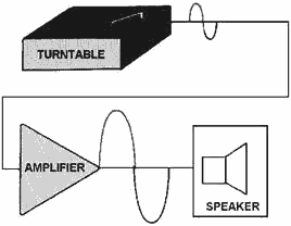
Figure 1-1 - Amplifier as used with turntable and speaker.

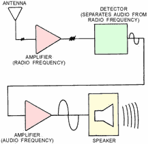
Figure 1-2 - Amplifiers as used in radio receiver.
Most electronic devices use amplifiers to provide various amounts of signal amplification.
Since most signals are originally too small to control or drive the desired device,
some amplification is needed.
For example, the audio signal taken from a record
is too small to drive a speaker, so amplification is needed. The signal will be
amplified several times between the needle of the record player and the speaker.
Each time the signal is amplified it is said to go through a Stage of amplification.
The audio amplifier shown connected between the turntable and speaker system in
figure 1-1 contains several stages of amplification.
Notice the triangle used in figure 1-1 to represent the amplifier. This triangle
is the standard block diagram symbol for an amplifier.
Another example of the use of an amplifier is shown in figure 1-2. In a radio
receiver, the signal picked up by the antenna is too weak (small) to be used as
it is. This signal must be amplified before it is sent to the detector. (The detector
separates the audio signal from the frequency that was sent by the transmitter.
The way in which this is done will be discussed later in this training series.)
The audio signal from the detector will then be amplified to make it large enough
to drive the speaker of the radio.
Almost every electronic device contains at least one stage of amplification,
so you will be seeing amplifiers in many devices that you work on. Amplifiers will
also be used in most of the NEETS modules that follow this one.
Q-1. What is amplification?
Q-2. Does an amplifier actually change an input signal? Why or why not?
Q-3. Why do electronic devices use amplifiers?
Classification of Amplifiers
Most electronic devices use at least one amplifier, but there are many types
of amplifiers. This module will not try to describe all the different types of amplifiers.
You will be shown the general principles of amplifiers and some typical amplifier
circuits.
Most amplifiers can be classified in two ways. The first classification is by
their function. This means they are basically voltage amplifiers or power amplifiers.
The second classification is by their frequency response. In other words what frequencies
are they designed to amplify?
If you describe an amplifier by these two classifications (function and frequency
response) you will have a good working description of the amplifier. You may not
know what the exact circuitry is, but you will know what the amplifier does and
the frequencies that it is designed to handle.
Voltage Amplifiers and Power Amplifiers
All amplifiers are current-control devices. The input signal to an amplifier
controls the current output of the amplifier. The connections of the amplifying
device (electron tube, transistor, magnetic amplifier, etc.) and the circuitry of
the amplifier determine the classification. Amplifiers are classified as voltage
or power amplifiers.
Voltage Amplifier is an amplifier in which the output
signal voltage is larger than the input signal voltage. In other words, a voltage
amplifier amplifies the voltage of the input signal.
A Power Amplifier is an amplifier in which the output signal
power is greater than the input signal power. In other words, a power amplifier
amplifies the power of the input signal. Most power amplifiers are used as the final
amplifier (stage of amplification) and control (or drive) the output device. The
output device could be a speaker, an indicating device, an antenna, or the heads
on a tape recorder. Whatever the device, the power to make it work (or drive it)
comes from the final stage of amplification which is a power amplifier.

Figure 1-3A - Block diagram of voltage and power amplifiers.

Figure 1-3B - Block diagram of voltage and power amplifiers.
Figure 1-3 shows a simple block diagram of a voltage amplifier with its input
and output signals and a power amplifier with its input and output signals. Notice
that in view (A) the output signal voltage is larger than the input signal voltage.
Since the current values for the input and output signals are not shown, you cannot
tell if there is a power gain in addition to the voltage gain.
In view (B) of the figure the output signal voltage is less than the input signal
voltage. As a voltage amplifier, this circuit has a gain of less than 1. The output
power, however, is greater than the input power. Therefore, this circuit is a power
amplifier.
The classification of an amplifier as a voltage or power amplifier is made by
comparing the characteristics of the input and output signals. If the output signal
is larger in voltage amplitude than the input signal, the amplifier is a voltage
amplifier. If there is no voltage gain, but the output power is greater than the
input power, the amplifier is a power amplifier.
Frequency Response of Amplifiers
In addition to being classified by function, amplifiers are classified by frequency
response. The frequency response of an amplifier refers to the band of frequencies
or frequency range that the amplifier was designed to amplify.
You may wonder why the frequency response is important. Why doesn't an amplifier
designed to amplify a signal of 1000 Hz work just as well at 1000 MHz? The answer
is that the components of the amplifier respond differently at different frequencies.
The amplifying device (electron tube, transistor, magnetic amplifier, etc.) itself
will have frequency limitations and respond in different ways as the frequency changes.
Capacitors and inductors in the circuit will change their reactance as the frequency
changes. Even the slight amounts of capacitance and inductance between the circuit
wiring and other components (interelectrode capacitance and self-inductance) can
become significant at high frequencies. Since the response of components varies
with the frequency, the components of an amplifier are selected to amplify a certain
range or band of frequencies.
Note: For explanations of interelectrode capacitance and self-inductance see
NEETS Modules 2 - Introduction to Alternating Current and Transformers; 6 - Introduction
to Electronic Emission, Tubes, and Power Supplies; and 7 - Introduction to Solid-State
Devices and Power Supplies.
The three broad categories of frequency response for amplifiers are Audio Amplifier,
RF Amplifier, and Video Amplifier.
An audio amplifier is designed to amplify frequencies between 15 Hz and 20 kHz.
Any amplifier that is designed for this entire band of frequencies or any band of
frequencies contained in the audio range is considered to be an audio amplifier.
In the term RF amplifier, the "RF" stands for radio frequency. These amplifiers
are designed to amplify frequencies between 10 kHz and 100,000 MHz. a single amplifier
will not amplify the entire RF range, but any amplifier whose frequency band is
included in the RF range is considered an RF amplifier.
A video amplifier is an amplifier designed to amplify a band of frequencies from
10 Hz to 6 MHz. Because this is such a wide band of frequencies, these amplifiers
are sometimes called Wide-Band Amplifiers. While a video amplifier will amplify
a very wide band of frequencies, it does not have the gain of narrower-band amplifiers.
It also requires a great many more components than a narrow-band amplifier to enable
it to amplify a wide range of frequencies.
Q-4. In what two ways are amplifiers classified?
Q-5. What type of amplifier would be used to drive the speaker system of a record
player?
Q-6. What type of amplifier would be used to amplify the signal from a radio
antenna?
Transistor Amplifiers
A transistor amplifier is a current-control device. The current in the base of
the transistor (which is dependent on the emitter-base bias) controls the current
in the collector. a vacuum-tube amplifier is also a current-control device. The
grid bias controls the plate current. These facts are expanded upon in NEETS Module
6, Introduction to Electronic Emission, Tubes and Power Supplies, and Module 7,
Introduction to Solid-State Devices and Power Supplies.
You might hear that a vacuum tube is a voltage-operated device (since the grid
does not need to draw current) while the transistor is a current-operated device.
You might agree with this statement, but both the vacuum tube and the transistor
are still current-control devices. The whole secret to understanding amplifiers
is to remember that fact. Current control is the name of the game. Once current
is controlled you can use it to give you a voltage gain or a power gain.
This chapter will use transistor amplifiers to present the concepts and principles
of amplifiers. These concepts apply to vacuum-tube amplifiers and, in most cases,
magnetic amplifiers as well as transistor amplifiers. If you wish to study the vacuum-tube
equivalent circuits of the transistor circuits presented, an excellent source is
the EIMB, NAVSEA 0967-LP-000-0120, Electronics Circuits.
The first amplifier concept that is discussed is the "class of operation" of
an amplifier.
Amplifier Classes of Operation
The class of operation of an amplifier is determined by the amount of time (in
relation to the input signal) that current flows in the output circuit. This is
a function of the operating point of the amplifying device. The operating point
of the amplifying device is determined by the bias applied to the device. There
are four classes of operation for an amplifier. These are: A, AB, B and C. Each
class of operation has certain uses and characteristics. No one class of operation
is "better" than any other class. The selection of the "best" class of operation
is determined by the use of the amplifying circuit. The best class of operation
for a phonograph is not the best class for a radio transmitter.
Class A Operation

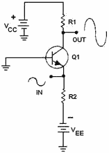
Figure 1-4 - A simple class a transistor amplifier.

Figure 1-5 - a simple class AB transistor amplifier.
A simple transistor amplifier that is operated class a is shown in figure 1-4.
Since the output signal is a 100% (or 360º) copy of the input signal, current in
the output circuit must flow for 100% of the input signal time. This is the definition
of a class a amplifier. Amplifier current flows for 100% of the input signal.
The class a amplifier has the characteristics of good Fidelity and low Efficiency.
Fidelity means that the output signal is just like the input signal in all respects
except amplitude. It has the same shape and frequency. In some cases, there may
be a phase difference between the input and output signal (usually 180º), but the
signals are still considered to be "good copies." If the output signal is not like
the input signal in shape or frequency, the signal is said to be Distorted. Distortion
is any undesired change in a signal from input to output.
The efficiency of an amplifier refers to the amount of power delivered to the
output compared to the power supplied to the circuit. Since every device takes power
to operate, if the amplifier operates for 360º of input signal, it uses more power
than if it only operates for 180º of input signal. If the amplifier uses more power,
less power is available for the output signal and efficiency is lower. Since class
a amplifiers operate (have current flow) for 360º of input signal, they are low
in efficiency. This low efficiency is acceptable in class a amplifiers because they
are used where efficiency is not as important as fidelity.
Class AB Operation
If the amplifying device is biased in such a way that current flows in the device
for 51% - 99% of the input signal, the amplifier is operating class AB. a simple
class AB amplifier is shown in figure 1-5.
Notice that the output signal is distorted. The output signal no longer has the
same shape as the input signal. The portion of the output signal that appears to
be cut off is caused by the lack of current through the transistor. When the emitter
becomes positive enough, the transistor cannot conduct because the base- to-emitter
junction is no longer forward biased. Any further increase in input signal will
not cause an increase in output signal voltage.
Class AB amplifiers have better efficiency and poorer fidelity than class a amplifiers.
They are used when the output signal need not be a complete reproduction of the
input signal, but both positive and negative portions of the input signal must be
available at the output.
Class AB amplifiers are usually defined as amplifiers operating between class
A and class B because class a amplifiers operate on 100% of input signal and class
B amplifiers (discussed next) operate on 50% of the input signal. Any amplifier
operating between these two limits is operating class AB.
Class B Operation

Figure 1-6 - a simple class B transistor amplifier.

Figure 1-7 - a simple class C transistor amplifier.
As was stated above, a class B amplifier operates for 50% of the input signal.
A simple class B amplifier is shown in figure 1-6.
In the circuit shown in figure 1-6, the base-emitter bias will not allow the
transistor to conduct whenever the input signal becomes positive. Therefore, only
the negative portion of the input signal is reproduced in the output signal. You
may wonder why a class B amplifier would be used instead of a simple rectifier if
only half the input signal is desired in the output. The answer to this is that
the rectifier does not amplify. The output signal of a rectifier cannot be higher
in amplitude than the input signal. The class B amplifier not only reproduces half
the input signal, but amplifies it as well.
Class B amplifiers are twice as efficient as class a amplifiers since the amplifying
device only conducts (and uses power) for half of the input signal. a class B amplifier
is used in cases where exactly 50% of the input signal must be amplified. If less
than 50% of the input signal is needed, a class C amplifier is used.
Class C Operation
Figure 1-7 shows a simple class C amplifier. Notice that only a small portion
of the input signal is present in the output signal. Since the transistor does not
conduct except during a small portion of the input signal, this is the most efficient
amplifier. It also has the worst fidelity. The output signal bears very little resemblance
to the input signal.
Class C amplifiers are used where the output signal need only be present during
part of one-half of the input signal. Any amplifier that operates on less than 50%
of the input signal is operated class C.
Q-7. What determines the class of operation of an amplifier?
Q-8. What are the four classes of operation of a transistor amplifier?
Q-9. If the output of a circuit needs to be a complete representation of one-half
of the input signal, what class of operation is indicated?
Q-10. Why is class C operation more efficient than class a operation?
Q-11. What class of operation has the highest fidelity?
Amplifier Coupling
Earlier in this module it was stated that almost every electronic device contains
at least one stage of amplification. Many devices contain several stages of amplification
and therefore several amplifiers. Stages of amplification are added when a single
stage will not provide the required amount of amplification. For example, if a single
stage of amplification will provide a maximum gain of 100 and the desired gain from
the device is 1000, two stages of amplification will be required. The two stages
might have gains of 10 and 100, 20 and 50, or 25 and 40. (The overall gain is the
product of the individual stages-10 x 100 = 20 x 50 = 25 x 40 = 1000.)

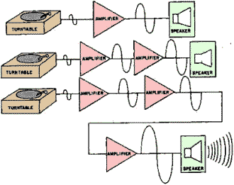
Figure 1-8 - Adding stages of amplification.
Figure 1-8 shows the effect of adding stages of amplification. As stages of amplification
are added, the signal increases and the final output (from the speaker) is increased.
Whether an amplifier is one of a series in a device or a single stage connected
between two other devices (top view, figure 1-8), there must be some way for the
signal to enter and leave the amplifier. The process of transferring energy between
circuits is known as Coupling. There are various ways of coupling signals into and
out of amplifier circuits. The following is a description of some of the more common
methods of amplifier coupling.
Direct Coupling
The method of coupling that uses the least number of circuit elements and that
is, perhaps, the easiest to understand is direct coupling. In direct coupling the
output of one stage is connected directly to the input of the following stage. Figure
1-9 shows two direct-coupled transistor amplifiers.
Posted November 2, 2021
|


