Module 6 - Introduction to Electronic Emission, Tubes, and Power
Supplies
Pages i,
1-1,
1-11,
1-21,
1-31,
1-41,
1-51,
2-1,
2-11,
2-21,
2-31,
3-1,
3-11,
3-21,
3-31,
3-41,
3-51, AI-1, Index
troubles that you should
keep in mind. The meaning of each trouble will be clear by the time you end your study of vacuum tubes, even
though you may not quite understand them now. 1. The filament, after long service, may be unable to
emit as many electrons as are required for proper operation. 2. The filament may burn out.
3. a tube element-the plate, for instance-may break its connection with the tube base pin. 4. Two
elements, such as filament and plate, may short together.
5. The tube may become gassy. The symptoms you will come across in signal tracing will be
many and varied. You will need to combine your "know-how" of the circuit and your knowledge of these five possible
tube troubles to determine if the tube could in some way be causing the symptoms. If you suspect the tube of
causing trouble, either try another tube in its place or check it on a tube tester. But remember, the final check
of whether or not the old tube was bad is whether or not the equipment works properly when a good tube is put in
its place. Therefore, putting in a good tube and then trying out the equipment is the best check.
Transformer and Choke Troubles As you should know by now, the transformer and choke are
quite similar in construction. Therefore, it is no coincidence that the basic troubles they can develop are the
same. 1. a winding can open. 2. Two or more turns of one winding can short together.
3. a winding can short to the casing, which is usually grounded. 4. Two windings can short
together. This trouble is possible, of course, only in transformers.

As with the tube, the symptoms of these troubles will vary with the type of circuit. However, when you
have decided that one of these four possible troubles could be causing the symptoms, there are definite steps to
take. If you surmise that there is an open winding or windings shorted together or to ground, an ohmmeter
continuity check will locate the trouble. If the turns of a winding are shorted together, you may not be able to
detect a difference in winding resistance. Therefore, you need to connect a good transformer in the place of the
old one and see if the symptoms are eliminated; but keep in mind that transformers are difficult to replace. Make
absolutely sure that the trouble is not elsewhere in the circuit before you change the transformer.
Occasionally, shorts will appear only when operating voltages are applied to the transformer. In this case you
might find the trouble with a megger - an instrument that applies a high voltage as it reads resistance.
3-51
Capacitor and Resistor Troubles Only two things can happen to a capacitor:
1. It may open up, removing itself completely from the circuit. 2. It may develop an internal
short circuit. This means that it begins to pass current as though it were a resistor or a direct short.

You can check a capacitor you suspect of being open by disconnecting it from the circuit and checking it
with a capacitor analyzer. You can check a capacitor you suspect of being leaky with an ohmmeter; if it reads less
than 500 kilohms, it is more than likely bad. However, capacitor troubles are difficult to find since they may
appear intermittently or only under operating voltages. Therefore, the best check for a faulty capacitor is to
replace it with one you know to be good. If this restores proper operation, the fault was in the capacitor.
Resistor troubles are the simplest; but like the rest, you must keep them in mind. 1. a resistor can
open up. 2. a resistor can increase in value. 3. a resistor can decrease in value.

You already know how to check possible resistor troubles. Just use an ohmmeter after making sure no
parallel circuit is connected across the resistor you wish to measure. When you know a parallel circuit is
connected across the resistor or when you are in doubt, disconnect one end of the resistor before measuring it.
The ohmmeter check will usually be adequate. However, never forget that intermittent troubles may develop in
resistors as well as in any other electronic parts. Also remember that the final
3-52
proof that a resistor is bad is when you replace it with another resistor and the equipment operates
satisfactorily.
Although you may observe problems that we have not covered specifically in this chapter, you should have
gained enough knowledge to localize and repair any problem that may occur. Q43. What is the most
important thing to remember when troubleshooting? Q44. What is the main reason for grounding the return
side of the transformer to the chassis? Q45. What are two types of checks used in troubleshooting power
supplies?
Summary In this chapter, we have presented you a basic description of the theory and operation of a basic power
supply and its components. The following summary should enhance your understanding of power supplies.
Power SUPPLIES are electronic circuits designed to convert ac to dc at any desired level. Almost
all power supplies are composed of four sections: transformer, rectifier, filter, and regulator.

The Power Transformer is the input transformer for the power supply. In addition to the
high voltage, the power transformer also supplies filament voltage.

The RECTIFIER is the section of the power supply that contains the secondary windings
of the power transformer and the rectifier circuit. The rectifier uses the ability of a diode to conduct during
one half cycle of ac to convert ac to dc.
3-53
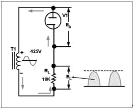
Half-WAVE RECTIFIERS give an output on only one half cycle of the input ac. For this reason,
the pulses of dc are separated by a period of one half cycle of zero potential voltage.

FULL-WAVE RECTIFIERS conduct on both halves of the input ac cycles. As a result, the dc
pulses are not separated from each other. a characteristic of full-wave rectifiers is the use of a center- tapped,
high-voltage secondary. Because of the center tap, the output of the rectifier is limited to one-half of the input
voltage of the high-voltage secondary.

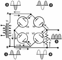
BRIDGE RECTIFIERS are full-wave rectifiers that do not use a center-tapped,
high-voltage secondary. Because of this their dc output voltage is equal to the input voltage from the
high-voltage secondary of the power transformer. Bridge rectifiers use four diodes connected in a bridge network.
Tubes conduct in diagonal pairs to give a full-wave pulsating dc output.
3-54

FILTER Circuits are designed to smooth, or filter, the ripple voltage present on the
pulsating dc output of the rectifier. This is done by an electrical device that has the ability to store energy
and to release the stored energy. Capacitance FILTERS are nothing more than large
capacitors placed across the output of the rectifier section. Because of the large size of the capacitors, fast
charge paths, and slow discharge paths, the capacitor will charge to average value, which will keep the pulsating
dc output from reaching zero volts.

INDUCTOR FILTERS use an inductor called a choke to filter the pulsating dc input.
Because of the impedance offered to circuit current, the output of the filter is at a lower amplitude than the
input.
3-55

PI-TYPE FILTERS use both capacitive and inductive filters connected in a pi-type
configuration. Because of the combination of filtering devices, the ability of the pi filter to remove ripple
voltage is superior to that of either the capacitance or inductance filter.

Voltage REGULATORS are circuits designed to maintain the output of power supplies at a
constant amplitude despite variations of the ac source voltage or changes of the resistance of the load. This is
done by creating a voltage divider of a resistive element in the regulator and the resistance of the load.
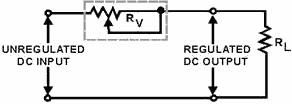
Regulation is achieved by varying the resistance of the resistive element in the regulator. A
Series REGULATOR uses a variable resistance in series with the load. Regulation is achieved by varying this resistance either to
increase or decrease the voltage drop across the resistive element of the regulator. Characteristically, the
resistance of the variable resistance moves in the same direction as the load. When the resistance of the load
increases, the variable resistance of the regulator increases; when load resistance decreases, the variable
resistance of the regulator decreases.

3-56
Shunt REGULATORS use a variable resistance placed in parallel with the load.
Regulation is achieved by keeping the resistance of the load constant. Characteristically, the resistance of the
shunt moves in the opposite direction of the resistance of the load.

VR-TUBE REGULATORS are shunt regulators that use a cold cathode as a variable
resistance in parallel with the load. Because of their ability to maintain a constant voltage potential between
their plates and cathode, glow tubes can be connected in series to regulate any voltage. Additionally, glow tubes
can be used to deliver different voltages to different loads.

SIMPLE ELECTRON TUBE REGULATORS use the dc plate resistance of a triode as a variable
resistance in series with the load. The resistance of the vacuum tube is varied by changing the amount of
conduction of the tube. This is done by holding the control grid voltage at a constant level and allowing the
cathode voltage to vary with the output voltage.

The AMPERITE Voltage REGULATOR or BALLAST TUBE is normally used to
control current surges. This is done by heating an iron wire in a hydrogen-filled envelope. The hot iron will
present a large resistance to current flow.
3-57

Answers to Questions Q1. Through Q45. A1. Transformer, rectifier, filter, regulator. A2. To maintain a constant voltage to the
load. A3. It couples the power supply to the ac line voltage, isolates the ac line voltage from the
load, and steps this voltage up or down to the desired level. A4. Filament voltage to the electron
tubes. A5. Provides capability of developing two high-voltage outputs. A6. Positive.
A7. Cutoff. A8. Pulsating dc. A9. Series. A10. 60 hertz. A11. Eavg
= 0.318 × Emax. A12. 120 hertz. A13. 63.6 volts. A14. The peak voltage is
half that of a half-wave rectifier.
3-58
A15. The bridge rectifier can produce double the voltage with the same size transformer.
A16. Decrease-Capacitance is inversely proportional to XC. A17. Capacitor.
A18. Parallel. A19. High. A20. Increase.
A21. Value of capacitance and load resistance. A22. Good. A23. Yes. A24. Counter
electro-motive force of the inductor. A25. 1 to 20 henries. A26. Decrease. A27.
Small. A28. Expense. A29. When ripple must be held at an absolute minimum. A30. LC
capacitor-input filter. A31. Cost of the inductor and size of the inductor.
A32. Ac line voltage and a change in load resistance. A33. Percent of regulator.
A34. 33.33% A35. 0%. A36. Variation. A37. Series and shunt. A38.
Increase. A39. Parallel. A40. Variable resistor. A41. Current regulation.
A42. Decrease.
A43. Safety precautions.
3-59
A44. Reduce the cost of manufacturing equipment. A45. Visual and signal tracing.
3-60
| - |
Matter, Energy,
and Direct Current |
| - |
Alternating Current and Transformers |
| - |
Circuit Protection, Control, and Measurement |
| - |
Electrical Conductors, Wiring Techniques,
and Schematic Reading |
| - |
Generators and Motors |
| - |
Electronic Emission, Tubes, and Power Supplies |
| - |
Solid-State Devices and Power Supplies |
| - |
Amplifiers |
| - |
Wave-Generation and Wave-Shaping Circuits |
| - |
Wave Propagation, Transmission Lines, and
Antennas |
| - |
Microwave Principles |
| - |
Modulation Principles |
| - |
Introduction to Number Systems and Logic Circuits |
| - |
- Introduction to Microelectronics |
| - |
Principles of Synchros, Servos, and Gyros |
| - |
Introduction to Test Equipment |
| - |
Radio-Frequency Communications Principles |
| - |
Radar Principles |
| - |
The Technician's Handbook, Master Glossary |
| - |
Test Methods and Practices |
| - |
Introduction to Digital Computers |
| - |
Magnetic Recording |
| - |
Introduction to Fiber Optics |
| Note: Navy Electricity and Electronics Training
Series (NEETS) content is U.S. Navy property in the public domain. |
|


