Module 6 - Introduction to Electronic Emission, Tubes, and Power
Supplies
Pages i,
1-1,
1-11,
1-21,
1-31,
1-41,
1-51,
2-1,
2-11,
2-21,
2-31,
3-1,
3-11,
3-21,
3-31,
3-41,
3-51, AI-1, Index
According to Ohm's law,
the value of the load resistance for this circuit figure will be 900 ohms if a current of 100 milliamperes flows
through RL. The internal resistance of the VR tube can be calculated in a similar manner. With 22.5
milliamperes flowing and 90 volts dropped across the VR tube, its resistance is 4 kilohms. To determine
the voltage regulation in the circuit for figure 3-44, assume a constant supply voltage of 150 volts and a
variable load resistance. If the value of RL were to decrease to 857 ohms, the load current would
increase to approximately 105 milliamperes to maintain 90 volts across the load resistance. RS must
drop 60 volts. To do so requires a current of 122.5 milliamperes flowing through the series resistance. Since 105
milliamperes is now flowing through the load, the current through the VR tube must decrease from 22.5 milliamperes
to 17.5 milliamperes. We will discuss the sequence of events in more detail to help you better understand how the
tube current is made to vary. The original load resistance was 900 ohms. Changes in this resistance will
not occur instantaneously, but will require some time to vary from 900 ohms to a new value. As resistance of the
load begins to decrease, load current begins to increase. The minute increase in load current will flow through
the series resistance RS causing a slight increase in ERS. This slight increase in voltage
across RS will result in the VR tube voltage dropping slightly. This slight drop in tube voltage will
cause a decrease in the ionization of the tube gas, which in turn increases the resistance of the tube. As a
result, less current flows through the tube. Note that tube current can decrease only to a value of 5
milliamperes before deionization occurs. Therefore, the load current cannot exceed 117.5 milliamperes, for beyond
this value, tube current becomes less than 5 milliamperes and regulation ceases.
If load resistance were to increase, load current would decrease. This would result in the VR tube
current increasing to maintain a current of 122.5 milliamperes. The VR tube current can only increase to 40
milliamperes. Beyond this value of current, the tube enters the abnormal glow region and tube voltage increases.
The upper limit of the VR tube current will occur when load current decreases to a value of 82.5
milliamperes. When load current drops below this value, the VR tube ceases to regulate the load voltage.
Therefore, with a constant source voltage but variable load resistance, the limits of regulation will be reached
when current in the load exceeds 117.5 milliamperes or drops below 82.5 milliamperes. The VR tube
regulator can also compensate for changes in power supply voltage. Under these conditions, the load resistance
will remain constant while the power supply voltage will be variable. Refer to figure 3-44 for the following
discussion. Assume that the source voltage begins to increase from an original value of 150 volts toward
155 volts. As this voltage increases, current through RS increases from its original value of 122.5
milliamperes. Initially, this additional current is drawn from the load, causing a slight increase in load
voltage. This increase in load voltage is felt across the VR tube and causes an increase in tube ionization. This
decreases the internal resistance of the VR tube with a resultant increase in tube current. When source voltage
reaches 155 volts, current through RS is approximately 133 milliamperes (RS = 490 ohms). Most of the
additional current through RS flows through the VR tube. As a result, approximately 33 milliamperes
flows through the VR tube, maintaining the load voltage at 90 volts.
Since VR tube current decreases as source voltage decreases, tube current will drop below its lower limit of 5
milliamperes at some point. When source voltage drops below 141.4 volts, tube current will be less than 5
milliamperes and regulation will cease. The upper and lower limits of the supply voltage variations that can be
allowed and still provide regulation in the circuit are 158.6 volts and 141.4 volts,
3-41
respectively. Remember that tube voltage varies slightly through its operating range, but this voltage
change is less than that which would exist without the use of a VR tube. As the source voltage increases,
the current through the VR tube increases. Since the upper limit of tube current is 40 milliamperes, there is a
limit in the ability of the tube to regulate increasing voltage. When the supply voltage exceeds 158.6 volts, tube
current will be greater than 40 milliamperes and regulation will cease. If the source voltage decreases
from 150 volts to 145 volts, only 55 volts must be dropped across the 490-ohm series resistance (RS)
to maintain the load voltage at 90 volts. Current through RS for a 55 volt drop is 112 milliamperes.
Since load current is 100 milliamperes, the remaining 12 milliamperes must flow through the VR tube. This
represents a decrease in the ionization level of the VR tube, with a resultant increase in tube resistance. Under
these conditions, 90 volts will be maintained across the load resistance. VR Tubes Connected in
Series
In applications where a regulated voltage in excess of the maximum rating of one tube is required, two or more
tubes may be placed in series as shown in figure 3-45.
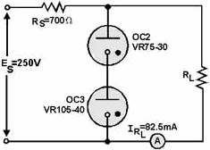
Figure 3-45. - VR tubes as voltage dividers. In the figure, a VR75-30 and a VR105-40 are shown connected in series. The source voltage is 250 volts,
and 82.5 milliamperes flows through the load resistance. Since current through the two VR tubes is common, the
limits of regulation are determined by the tube having the smaller current limitations. (In this case, the VR
75-30). In computing Imean for this circuit, Imax and Imin will be 30 milliamperes and 5 milliamperes,
respectively. Therefore, the mean current will be 17.5 milliamperes. The value of RS in the
figure can be computed using the source voltage of 250 volts and the total current through RS (load
current + Imean). Using these values, RS = 700 ohms. Note that the regulated voltage to the
load is 180 volts. This provides a regulated voltage greater than would be possible using either VR tube by
itself. Another advantage of using VR tubes in series is illustrated in figure 3-46. In this circuit,
several values of regulated voltages are obtained from a single power supply.
3-42
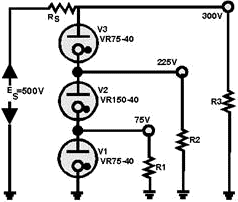
Figure 3-46. - VR tubes as voltage dividers The current flowing through V2 in the figure is a combination of the current through R1 and the current
through V1. The current through V3, on the other hand, is the sum of the currents through V2 and R2. Since V3 has
more current flowing through it than any of the other VR tubes, it places or determines the limit on the maximum
current in the VR tube circuit. Since the maximum rating of V3 is 40 milliamperes, the currents through R1 and R2
must be limited to only a few milliamperes, or the rating of V3 will be exceeded and regulation will cease.
The obvious advantage in using VR tubes in series is to provide several regulated voltages from a single power
supply. The primary disadvantage is in the current limitations. Since it is impossible to have all VR tubes
operating about their mean current values, this limits the ability of the circuit to regulate over wide ranges of
variations in load resistance or source voltage. VR Tubes Connected in Parallel
One might expect that connecting VR tubes in parallel as shown in figure 3-47 would increase the current handling
capacity of the network. Although this is true for some gas-filled tubes, it is not true for VR tubes. In figure
3-47, two VR tubes are constructed in exactly the same way. The only difference will be a slight variation in
their ionization potential. For the purpose of this discussion, VR tube VR1 will have a lower ionization potential
than VR2. The potential that must be reached before a VR tube ionizes is considerably higher than its normal
operating voltage.
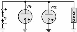
Figure 3-47. - VR tubes connected in parallel.
3-43
When voltage is applied to the circuit of figure 3-47, as soon as the correct potential is reached,
VR1 begins to conduct and the potential across it decreases to its operating voltage. The potential across VR2
never becomes high enough to cause it to ionize. Therefore, placing the VR tubes in parallel accomplishes no useful purpose. When greater current handling capacity and better regulation are desired, electronic (vacuum tube)
regulator circuits are used. Several conditions may either indicate or cause problems with a VR tube
regulator. Initially, you can get some indication of the trouble associated with a gas-tube regulator circuit by
visually inspecting it to determine the presence of the characteristic glow from the ionized gas within the tube.
When current through the tube is near its maximum rating, the tube is highly ionized. When the current is near its
minimum rating, the tube is lightly ionized, Therefore, the intensity of the gaseous discharge within the tube is
an indication of tube conduction. If the tube is not ionized, however, this does not necessarily mean that the
tube is defective. The same indication (lack of characteristic glow) may also result from the following
conditions: the series resistor (RS) has increased in value, the dc input voltage (ES) is below normal,
the load current is below normal, or the load current is excessive. You therefore need to make dc voltage
measurements at the input and output terminals of the voltage regulator circuit to determine whether the problem
is inside the regulator circuit or outside of it.
You can check value of the series resistor (RS) by using ohmmeter measurements to determine whether any
change in resistance has occurred. If the maximum current rating of the regulator tube is exceeded for a
considerable length of time, the tube may be damaged and lose its regulation characteristics; therefore, you can
suspect the regulator tube itself as a possible source of trouble. Although VR tubes are used extensively
in electronic equipment, there are circuits that require a greater degree of regulation than a VR tube can
provide. For these circuits, an electron tube voltage regulator is used. Electron Tube Voltage
Regulator
An electron tube may be considered a variable resistance. When the tube is passing a direct current, this
resistance is simply the plate-to-cathode voltage divided by the current through the tube and is called the dc
plate resistance (Rp). For a given plate voltage, the value of Rp depends upon the tube
current, and the tube current depends upon the grid bias. Refer to figure 3-48, view (A). The resistance
of V1 is established initially by the bias on the tube. Assume that the voltage across the load is at the desired
value. Then the cathode is positive with respect to ground by some voltage (EL). The grid can be made
positive relative to ground by a voltage (E2) that is less than E1. The potentiometer R2 is adjusted until the
bias (grid-to-cathode voltage), which is E2 - E1, is sufficient to allow V1 to pass a current equal to the desired
load current. With this bias, the resistance of V1 is established at the proper value to reduce the rectifier
output voltage to the desired load voltage.
3-44
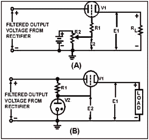
Figure 3-48. - Electron tube voltage regulator using a battery for the fixed bias If the rectifier output voltage increases, the voltage at the cathode of V1 tends to increase. As E1
increases, the negative bias on the tube increases and the plate resistance of the tube becomes greater.
Consequently, the voltage drop across V1 increases with the rise in input voltage. If the circuit is designed
property, the increased voltage drop across V1 is approximately equal to the increase in voltage at the input.
Thus the load voltage remains essentially constant. The resistor (R1) is used to limit the grid current.
This is necessary in this particular circuit because the battery is not disconnected when the power is turned off.
However, the battery can be eliminated from the circuit by the use of a glow tube (V2), as shown in view (B) of
the figure, to supply a fixed bias for the grid of the tube. The action of the circuit in view (B) is the same as
the action of the circuit in view (A). The output voltage of the simple voltage regulators shown in the figure
cannot remain absolutely constant. As the rectifier output voltage increases, the voltages on the cathode of V1
must rise slightly if the regulator is to function. The voltage regulators shown in the figure compensate
not only for changes in the output voltage from the rectifier, but also for changes in the load. For example, in
view (B) if the load resistance decreases, the load current will increase. The load voltage will tend to fall
because of the increased drop across V1. The decrease in load voltage is accompanied by a decrease in bias voltage
on V1. The bias voltage on V1 is equal to E1 - E2. Thus the effective resistance of V1 is reduced at the same time
the load current is increased. The IR drop across V1 increases only a slight amount because R decreases about as
much as I increases. Therefore, the tendency for the load voltage to drop when the load is increased is checked by
the decrease in resistance of the series triode. Q40. In an electron tube regulator, the electron tube
replaces what component?
3-45
CURRENT REGULATION Before we go to the next section, there is one type of
regulation that we should discuss-current regulation. In most power supplies, current is not regulated directly.
Fuses and other circuit protection devices are used to set an upper limit on the amount of current that can flow
in a power supply. Once this limit is exceeded, the fuse simply opens and the power supply is deenergized. Beyond
this, current is usually left unregulated because the load will draw from the power supply only the amount of
current that it needs. Decreases and increases in the power supply voltage caused by the variations in load
current are usually controlled by the voltage regulator. The Amperite Regulator
There are some cases in which current must be regulated or kept at a relatively constant value. The best example
of this is the filament supply of a power transformer located in a power supply that is designed to supply
filament power to many tubes. You can see this in view (A) of figure 3-49, which is a portion of a power supply
designed to supply 50 vacuum tubes with both plate and filament voltages. Under normal conditions, circuit current
will not exceed 2.5 amperes. For this reason, the power supply has been fused at 3 amperes. Because you are only
interested in current regulation at this time, only the portion of the power supply that deals with current
regulation is shown; namely, the power transformer and four of the 50 parallel connected vacuum-tube filaments. At
operating temperatures, the resistance of each filament is 1 kilohm. Because the filaments are connected in
parallel, the total filament resistance at operating temperature is 20 ohms. Ohm's law,
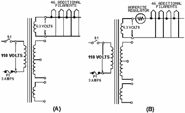
Figure 3-49. - Amperite regulator. 3-46
tells you that the filaments draw .315 amperes. You should know from your previous study that as
conductors are heated, their resistance increases. Therefore, the cold resistance of the filaments is considerably
lower than the hot resistance. In this case, assume 100 ohms per filament. The total resistance of the 50 parallel
filaments is then 2 ohms when the power supply is first energized, and the filaments draw 3.15 amperes of current.
If the current for the rest of the power supply is added to the filament current, the surge current will cause the
power supply to draw 5 amperes when it is first energized. Unfortunately, the power supply is fused at 3 amperes.
Under these conditions, it would be impossible to keep the power supply on the line long enough to get the
filaments up to operating temperature.
There are three possible solutions to this problem. The first is simply to fuse the power supply at 5
amperes, but this could allow excessive current to flow in the power supply. Another solution is to use a
slow-blow fuse. Unfortunately, the duration of the current surge may exceed the time limit that a slow- blow fuse
can handle. Therefore, current regulation is the best solution to this problem. Because of its
quick-heating ability, the amperite tube is ideal as a current regulator. The amperite regulator is nothing more
than an iron wire enclosed in a hydrogen-filled envelope. Because of its construction, the iron filament will heat
quickly when current is applied to it. View (B) of figure 3-49 shows the amperite regulator connected in
series with the filaments of the load. When the power supply is first energized, the iron wire of the amperite
gets hot quickly and presents a large resistance connected in series with the 2 ohms of filament resistance. As a
result, most of the voltage is dropped across the amperite. Because of the large resistance of the amperite
regulator, current in the circuit is held to an acceptable level in accordance with Ohm's law:

As the filaments warm up, their resistance increases, which causes circuit current to decrease. The
decreasing circuit current allows the iron wire of the amperite to cool. As it cools, its resistance decreases
until it reaches the approximate resistance of the circuit wiring. You might think that decreasing the resistance
of the amperite would allow circuit current to increase again, but this does not happen. As the iron wire of the
amperite cools and its resistance decreases, the resistance of the warming tube filaments increases. Throughout
the entire heating cycle of the filaments, the total resistance of the series circuit, consisting of the amperite
and tube filaments, remains fairly constant. When power is first applied, most of the resistance is in the
amperite. Therefore, most of the voltage is dropped across the resistance of the amperite. Halfway through the
cycle, the resistance of the amperite and the resistance of the filaments are approximately equal, and the voltage
drops across the two series elements are equal. Finally, when the filaments have reached their operating
temperature, most of the resistance is in the filaments of the tube. Therefore, most of the voltage is dropped
across the tube filaments. The important thing to note is that the total circuit resistance remains
approximately the same throughout the heating cycle. As the cycle progresses, the resistance of the amperite
decreases as the resistance of the tube filaments increases. Because resistance and voltage (6.3 volts) remain
constant, current remains constant, except for the slight surge in the beginning of the heating cycle, which is
necessary to heat up the iron wire of the amperite.
Now that we have discussed the different types of regulators, you should be able to see that there are many
variables that affect good regulation. Although you may not be required to design regulators, you will be
required to maintain them because your electronic equipment depends upon good regulation to operate property.
3-47
Up to this point we have discussed only the individual sections of the electron tube power supply. In
the next section, we will discuss the techniques of troubleshooting these individual sections and the total power
supply. Q41. What is the purpose of the amperite regulator? Q42. As the tube filaments in the
load heat up, will the circuit current increase or decrease?
TROUBLESHOOTING Power SUPPLIES Whenever you work with electricity, you must follow all the appropriate safety precautions. In the front
of all electronic technical manuals, you will always find a section on safety precautions. You should also find
posted on each piece of equipment a sign listing the specific precautions for that equipment. One hazardous area
that is sometimes overlooked, especially on board ship, is grounding of equipment. By grounding the return side of
the power transformer to the metal chassis, manufacturers can wire the cathodes of the tubes in both the power
supply and the load being supplied by the power supply directly to the metal chassis. This eliminates the
necessity of wiring each tube directly to the return side of the transformer, saving wire, and reducing the cost
of building the equipment. While this solves one of the problems of the manufacturer, it creates a problem for
you, the technician. Unless the chassis is physically grounded to the ship's ground (the hull), the chassis can be
charged (or can float) several hundred volts above ship's ground. If you come in contact with the metal chassis at
the same time you are in contact with the ship's hull, the current from the chassis can use your body as a low
resistance path back to the ship's ac generators. At best this can be an unpleasant experience; at worst it can be
fatal. For this reason Navy electronic equipment is always grounded to the ship's hull, and approved rubber mats
are required in all spaces where electronic equipment is present. Therefore, before you start to work on any
electronic or electrical equipment ALWAYS ENSURE THAT The Equipment and ANY Test Equipment
YOU ARE USING Is PROPERLY Grounded and THAT The RUBBER MAT YOU ARE Standing ON Is IN GOOD CONDITION. As
long as you follow these simple rules, you should be able to avoid the possibility of becoming an electrical
conductor. TESTING
There are two widely used checks in testing electronic equipment. The first is the VIsUAL CHECK.
Do not underestimate the importance of this check. Many technicians find defects right away simply by looking for
them. a visual check does not take long; in fact you should be able to see the problem in about 2 minutes if it is
the kind of problem that can be seen. You should learn the following procedure. You will find yourself using it
quite often, as it is good not only for power supplies but also for any other type of electronic equipment you may
be troubleshooting.
1. BEforE YOU PLUG IN The Equipment, LOOK for: a.
LOOSE TUBES - a tube that is not properly seated in its socket may not be making proper
contact with the rest of the circuit. It may very well be the source of your problem. Push the tube completely
into place. b. ShortS - Examine any terminal or connection that is close to
the chassis or to any other terminal for the possibility of a short. a short in any part of the power supply can
cause considerable damage. Look for and remove any stray drops of solder, bits of wire, nuts, or screws. It
sometimes helps to shake the chassis and listen for any tell-tale rattles. Remember to correct any problem that
may cause a short circuit. If it is not causing trouble now, it may cause problems in the future.
3-48
c. DIsCOLORED OR LEAKING Transformer - This is a sure sign that there is
a short somewhere. Locate it. If the equipment has a fuse, find out why the fuse did not blow; too large a size
may have been installed, or there may be a short across the fuse holder. d.
LOOSE, BROKEN, OR CORRODED CONNECTIONS - Any connection that is not in good condition
is a trouble spot If it is not causing problems now, it probably will in the future. Fix it. e.
DAMAGED ResistorS OR Capacitors - a resistor that is discolored or charred has been
subjected to an overload. An electrolytic capacitor will show a whitish deposit at the seal around the terminals.
Check for a short whenever you notice a damaged resistor or capacitor. If there is no short, the trouble may be
that the power supply has been overloaded in some way. Make a note to replace the part after signal tracing. There
is no sense in risking a new part until you have located the trouble. 2. PLUG IN The Power
SUPPLY and LOOK for: a. SMOKING PARTS - If any part smokes or if
you hear any boiling or sputtering sounds, pull the plug immediately. There is a short circuit somewhere that you
have missed in your first inspection. use an ohmmeter to check the part again; begin in neighborhood of the
smoking part. b. COLD TUBES - After allowing the equipment about two
minutes for warm-up, touch all the tubes. If a tube is cold, it is either burned out or there is a break in the
heater connections and the tube is not receiving proper heater voltage. Remove the tube and connect an ohmmeter
across the heater terminals to see if the filament is open (reads almost infinite resistance). If the filament
reads open, it is burned out. Replace the bad tube with a good one. If the filament reads a low resistance, this
indicates that the filament is all right. use an ac voltmeter to find the break between the filament and the
output of the transformer.
c. SPARKING - Tap or shake the chassis. If you see or hear sparking, you
have located a loose connection or a short. Check and repair the problem. If you locate and repair
any of the defects listed under the visual check, make a note of what you find and what you do to correct it. It
is quite probable you have found the trouble. However, a good technician takes nothing for granted. You must prove
to yourself that the equipment is operating properly and that no other troubles
exist. If you find none of the defects listed under the visual check, go ahead with the signal tracing
procedure. The trouble is probably of such a nature that you cannot see it directly with your eye-you must see it
through the eye of the oscilloscope. The second type of testing is signal tracing. Tracing the ac signal
through the equipment is the most rapid method of locating a trouble that you cannot find by a visual check. It
also serves as a check on any repairs you may have made. The idea is to trace the ac voltage from the transformer,
to see it change to pulsating dc at the rectifier tube filament, and then to see the pulsations smoothed out by
the filter. The point where the signal stops or becomes distorted is the place to look for the trouble.
Before you begin signal tracing, it is a good idea to measure the dc voltage. The dc output voltage should be in
the neighborhood of 340 volts. If you have no dc output voltage, you should look for an open or a short in your
signal tracing. If you have a low dc voltage, you should look for a defective part and keep your eyes open for the
place where the signal becomes distorted.
3-49
Signal tracing is done by observing the waveform at the input and output of each part of a circuit. It
is the method used to localize trouble in a circuit. Let's review what each part of a good power supply
does to the signal, as shown in figure 3-50. The ac voltage is brought in from the power line through the line
cord. This voltage is connected to the primary of the transformer through the ON-ofF switch (S1). At the secondary
winding of the transformer (points 1 and 2), the scope shows you a picture of the stepped-up voltage developed
across each half of the secondary winding - the picture is that of a complete sine wave. Each of the two stepped- up
voltages is connected between ground and one of the two plates of the rectifier tube. At the two rectifier plates
(points 4 and 5) there is still no change in the shape of the stepped-up voltage the scope picture still shows a
complete sine wave.
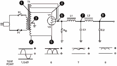
Figure 3-50. - Complete power supply (without regulator). However, when you look at the scope pattern for point 6 (the voltage at the rectifier heater), you see
the wave shape for pulsating direct current. This pulsating dc is fed through the first choke (L1) and filter
capacitor (C1), which remove a large part of the ripple or "hum," as shown by the waveform for point 7. Finally,
the dc voltage is fed through the second choke (L2) and filter capacitor (C2), which remove nearly all of the
remaining ripple. See the waveform for point 8, which shows almost no visible ripple. You now have almost pure dc.
No matter what power supplies you may encounter in the future, they all do the same thing - they change ac
voltage into dc voltage. COMPONENT PROBLEMS The following paragraphs will give
you an indication of troubles that occur with many different electronic circuit components.
Tube Troubles The symptoms of tube trouble will vary with every type of circuit and each
type of tube. However, the problems that can develop with a tube are common to every tube. Here are the five
possible tube
3-50
| - |
Matter, Energy,
and Direct Current |
| - |
Alternating Current and Transformers |
| - |
Circuit Protection, Control, and Measurement |
| - |
Electrical Conductors, Wiring Techniques,
and Schematic Reading |
| - |
Generators and Motors |
| - |
Electronic Emission, Tubes, and Power Supplies |
| - |
Solid-State Devices and Power Supplies |
| - |
Amplifiers |
| - |
Wave-Generation and Wave-Shaping Circuits |
| - |
Wave Propagation, Transmission Lines, and
Antennas |
| - |
Microwave Principles |
| - |
Modulation Principles |
| - |
Introduction to Number Systems and Logic Circuits |
| - |
- Introduction to Microelectronics |
| - |
Principles of Synchros, Servos, and Gyros |
| - |
Introduction to Test Equipment |
| - |
Radio-Frequency Communications Principles |
| - |
Radar Principles |
| - |
The Technician's Handbook, Master Glossary |
| - |
Test Methods and Practices |
| - |
Introduction to Digital Computers |
| - |
Magnetic Recording |
| - |
Introduction to Fiber Optics |
| Note: Navy Electricity and Electronics Training
Series (NEETS) content is U.S. Navy property in the public domain. |
|


