Module 6 - Introduction to Electronic Emission, Tubes, and Power
Supplies
Pages i,
1-1,
1-11,
1-21,
1-31,
1-41,
1-51,
2-1,
2-11,
2-21,
2-31,
3-1,
3-11,
3-21,
3-31,
3-41,
3-51, AI-1, Index
UHF TUBE TYPES
Uhf tubes have very small electrodes placed close together and often are manufactured without socket bases. By
reducing all the physical dimensions of the tube by the same scale, the interelectrode- capacitance and transit
time effects are reduced, without reducing the amplification capability of the tube. a disadvantage to this type
of tube construction is that the power-handling capability of these tubes is also reduced due to the close
placement of the tube elements.
Uhf tubes are placed in three broad categories based on their shape and/or construction; ACORN,
DOORKNOB, and PLANAR tubes. Acorn and Doorknob Tubes
ACORN TUBES, as shown in figure 2-10, are available for use as diodes, triodes, or pentodes.
Acorns are very small tubes that have closely spaced electrodes and no bases. The tubes are connected to their
circuits by short wire pins that are sealed in the glass or ceramic envelope. Because of their small size, acorn
tubes are usually used in low-power uhf circuits.

Figure 2-10. - Acorn tubes. The DOORKNOB TUBE is an enlarged version of the acorn tube. Because of its larger
physical size, it can be operated at higher power than the acorn tube. Planar Tubes
PLANAR TUBES are so named because of their construction. The ordinary (conventional) tube you
studied earlier uses concentric construction. This means that each element (cathode, grid, and plate) is
cylindrical in shape. The grid is placed over the cathode, and the plate, which is the largest cylinder, is
2-11
placed over the grid. The result is a tube composed of concentric cylinders like the one shown in
figure
2-11. Thus, the name concentric tubes.
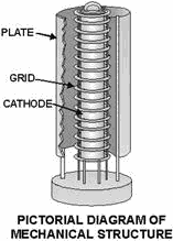
Figure 2-11. - Concentric construction of a conventional tube. At ultrahigh frequencies, the problems of producing small tube elements while reducing the spacing
between elements become very difficult. Not only are the elements hard to keep parallel with each other during the
manufacturing process, but they also have a tendency to warp and sag under normal operating conditions. Since
these elements are already as close together as possible, any reduction in element spacing can cause arcing.
Therefore, a new type of tube was developed to prevent arcing or element sagging in conventional tubes. This tube
is known as the planar tube. Planar tubes are electron tubes in which the cathode, plate, and grids are
mounted parallel to each other. Their physical construction greatly resembles a schematic diagram of a normal
tube, as shown in figure 2-12.
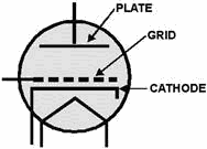
Figure 2-12. - Resemblance of a planar tube to a schematic diagram.
2-12
A typical planar tube is depicted in figure 2-13. Notice that the tube elements are mounted close to
each other and are parallel to one another. The oxide coating of the cathode is applied to the top surface only.
Therefore, the emitting surface of the cathode is parallel to the plate and the grid.
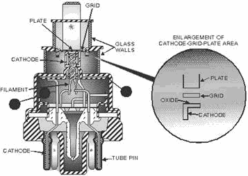
Figure 2-13. - Internal structure of a typical planar tube. The plate of the tube consists of a cylindrical stud. This stud-plate construction has two purposes. Its
flat lower surface serves as a parallel plate, and its external upper end serves as the external-plate connection
from the tube to the circuit. Because of its construction, the planar tube cannot use the ladder-type
grid, with which you are familiar. Instead, the grid, formed into a circle, is composed of a wire mesh similar to
that of a common screen door. The cathode structure is manufactured in two parts. Point a of figure 2-13
is the metallic shell of the tube and is used to couple (or connect) unwanted radio frequency signals from the
cathode to ground. This connection is not, however, a direct coupling. The wafer at point C of figure 2-13 is
composed of mica, which serves as a dielectric. The lower extension of the cathode serves as one plate of the
capacitor, while the other plate is formed from the flattened upper portion of the cathode connector ring. The
cathode has a direct connection to the tube pin through the connector labeled point B. You might think that this
is a rather complicated method to connect the cathode to a circuit, but it serves a purpose. At high
frequencies, the wiring of a circuit can pick up radio frequency signals and retransmit them. If the wiring
involved happens to be the wiring used to supply dc voltages to the circuit, all the tubes in the circuit will
receive the signal. The result will be massive distortion throughout the circuit. The problem can be
eliminated by isolating the dc and radio frequency circuits from each other. In planar tubes, this is fairly
simple. The point a ring is grounded. Any RF signals that the cathode may pick up through tube conduction are
grounded or shorted to ground through the capacitive coupling with the point a shell. In other words, the point a
shell (capacitive ground) serves the same function as the bypass
2-13
capacitor in a cathode-biased circuit. Because the capacitor will not pass dc, bias voltages can be
applied to the cathode through the tube pins. Notice the external shape of the planar tube in figure 2-13.
The tube is composed of five sections, or cylinders. As you go from the top to the bottom, each cylinder increases
in diameter. Because of this piled cylinder construction, the tube resembles a lighthouse, and is therefore known
as a LIGHTHouse TUBE. Another type of planar tube is shown in figure 2-14. This type of
tube, because of its external appearance, is called an OILCAN TUBE. The major difference between
it and the lighthouse tube is the addition of cooling fins to allow it to handle more power than the lighthouse
tube. Because of their planar construction, both types of tubes are capable of handling large amounts of power at
uhf frequencies.
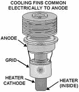
Figure 2-14. - Oilcan planar tube. Q6. What effect does transit time have on a conventional triode operated at uhf frequencies?
Q7. How do uhf tubes counter the effects of transit time? Q8. Why can acorn and
doorknob tubes NOT handle large amounts of power? Q9. What type of uhf tube was developed to handle
large amounts of power?
GAS-FILLED TUBES You know that great effort is made to produce a perfect vacuum within electron tubes. But, even the best
vacuum pumps and getters cannot remove all of the air molecules. However, the chances of an electron hitting a
molecule in a near-vacuum are very slim because of the great distance between the molecules, compared to the size
of the electron. An electron can pass between two molecules of air inside the tube as easily as a pea could pass
through a circle with a diameter equal to that of the earth! In some tubes, the air is removed and
replaced with an inert gas at a reduced pressure. The gases used include mercury vapor, neon, argon, and nitrogen.
Gas-filled tubes, as they are called, have certain
2-14
electrical characteristics that are advantageous in some circuits. They are capable of carrying much
more current than high-vacuum tubes, and they tend to maintain a constant IR drop across their
terminals within a limited range of currents. The principle of operation of the gas-filled tube involves the
process called
ionization. ELECTRICAL CONDUCTION IN GAS DIODES
An operating gas-filled tube has molecules, ions, and free electrons present within the envelope. In a gas-filled
diode, the electron stream from the hot cathode encounters gas molecules on its way to the plate. When an electron
collides with a gas molecule, the energy transmitted by the collision may cause the molecule to release an
electron. This second electron then may join the original stream of electrons and is capable of freeing other
electrons. This process, which is cumulative, is a form of ionization. The free electrons, greatly increased in
quantity by ionization, continue to the plate of the diode. The molecule which has lost an electron is called an
ion and bears a positive charge. The positive ions drift toward the negative cathode and during their journey
attract additional electrons from the cathode. The velocity of the electrons traveling toward the plate
varies directly with the plate voltage. If the plate voltage is very low, the gas-filled diode acts almost like an
ordinary diode except that the electron stream is slowed to a certain extent by the gas molecules. These
slower-moving electrons do not have enough energy to cause ionization when they hit the gas atoms. After the plate
voltage is raised to the proper level of conduction, the electrons have enough energy to cause ionization when
they hit the gas molecules. The plate potential at which ionization occurs is known as the IONIZATION
Point, or FIRING POTENTIAL, of a gas tube. If the plate voltage is reduced after
ionization, it can be allowed to go several volts below the firing potential before ionization (and hence,
high-plate current) win cease. The value of the plate voltage (Ep) at which ionization stops is called the
DEIONIZATION POTENTIAL, or EXTINCTION POTENTIAL. The firing point is always at a higher
plate potential than the deionization point. GAS TRIODE
The point at which the gas ionizes can be controlled more accurately by inserting a grid into the gas diode. a
negative voltage on the grid can prevent electrons from going to the plate, even when the plate voltage is above
the normal firing point. If the negative-grid voltage is reduced to a point where a few electrons are allowed
through the grid, ionization takes place. The grid immediately loses control, because the positive ions gather
about the grid wires and neutralize the grid's negative charge. The gas triode then acts as a diode. If the grid
is made much more negative in an effort to control the plate current, the only effect is that more ions collect
about the grid wires - tube continues to conduct as a diode. Only by removing the plate
potential or reducing it to the point where the electrons do not have enough energy to produce ionization
will tube conduction and the production of positive ions stop. Only after the production of positive ions is
stopped will the grid be able to regain control.
Such gas-filled triodes are known as THYRATRONS. Thyratrons are used in circuits where current
flow in the thyratrons output circuit is possible only when a certain amount of voltage is present on the
thyratrons grid. The flow of plate current persists even after the initiating grid voltage is no longer present at
the grid, and it can be stopped only by removing or lowering the plate potential. The symbols for the
gas-filled diode, the voltage regulator, and the thyratron are the same as those for high-vacuum tubes except that
a dot is placed within the envelope circle to signify the presence of gas. Some examples of gas-filled tube
schematic symbols are shown in figure 2-15.
2-15
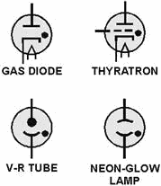
Figure 2-15. - Schematic diagram of gas-filled tubes. Before leaving this section, you should be aware of one precaution associated with mercury-vapor tubes.
The mercury vapor is not placed in the tube as a vapor; instead a small amount of liquid mercury is placed in the
tube before it is sealed. When the liquid mercury comes in contact with the hot filament, the mercury vaporizes.
To ensure that the mercury has vaporized sufficiently, the filament voltage must be applied to mercury-vapor tubes
for at least 30 seconds before the plate voltage is applied. If vaporization is incomplete, only partial
ionization is possible. Under these conditions, the application of plate voltage results in a relatively high
voltage drop across the tube (remember E = I × R), and the positive ions present are accelerated to a high
velocity in the direction of the cathode. As the ions strike the cathode, they tear away particles of the
emitting surface, usually causing permanent damage to the cathode and the tube. When the mercury is completely
vaporized, the action of the gas is such that the voltage drop across the tube can never rise above the
ionization potential (about 15 volts). At this low potential, positive-ion bombardment of the cathode does not
result in damage to the emitting surface.
Generally, when gas-filled tubes are in the state of ionization, they are illuminated internally by a soft, blue
glow. This glow is brightest in the space between the electrodes and of lesser intensity throughout the remainder
of the tube envelope. This glow is normal and must not be confused with the glow present in high-vacuum tubes when
gases are present. a high-vacuum tube with a bluish glow is gassy and should be replaced. The ionization of these
gases will distort the output of the tube and may cause the tube to operate with much higher plate current than it
can carry safely.
COLD-CATHODE TUBES The cold-cathode, gas-filled tube differs from the other types of gas-filled tubes in that it lacks
filaments. Thus, its name "COLD-CATHODE TUBE." In the tubes covered in this text thus far,
thermionic emission was used to send electrons from the cathode to the plate. This conduction of electrons can be
caused in another manner. If the potential between the plate and the cathode is raised to the point where tube
resistance is overcome, current will flow from the cathode whether it is heated or
2-16
not. In most applications in electronics, this method is not used because it is not as efficient as
thermionic emission. There are two applications where cold-cathode emission is used. The first application you are
already familiar with, although you may not be aware of it. Every time you look at a neon sign you are watching a
cold-cathode tube in operation. Thus, the first application of cold-cathode tubes is for visual display. You are
also familiar with the reason for this visual display. In the NEETS module on matter and
energy, we explained that when energy is fed into an atom (neon in this case), electrons are moved, or promoted,
to higher orbits. When they fall back, they release the energy that originally lifted them to their higher orbits.
The energy is in the form of light. Cold-cathode tubes are also used as Voltage REGULATORS.
Because voltage regulators will be dealt with extensively in the next chapter, we will not cover their operation
now. At this point, you only need to understand that a cold-cathode tube has the ability to maintain a constant
voltage drop across the tube despite changes of current flow through the tube. The tube does this by changing
resistance as current flow varies.
Examine figure 2-16. Here you see a cold-cathode tube connected to a variable voltage source. The variable
resistor Rkp does not exist as a physical component, but is used to represent the resistance between the cathode
and the plate. Most cold-cathode tubes have a firing point (ionizing voltage) at about 115 volts. Thus, the
tube in view a of the figure is below the firing point. Because the tube lacks thermionic emission capabilities,
no current will flow and the tube will have a resistance (rkp) near infinity. The potential difference between
the plate and ground under these conditions will be equal to the source (Ebb) voltage, as shown on the voltmeter.
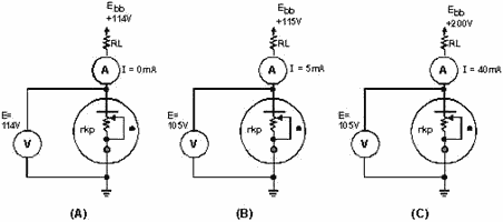
Figure 2-16. - Cold-cathode tube operation. In view B, the source voltage has been raised to the firing point of 115 volts. This causes the gas to
ionize and 5 milliamperes of current will flow through the tube. Because the tube represents a resistance (Rkp),
voltage will be dropped across the tube; in this case, 105 volts. The plate-load resistor (RL) will drop the
remaining 10 volts. The resistance of the tube at this time will be equal to:
2-17

In view C, the source voltage has been raised to 200 volts. This will cause more gas in the tube to
ionize and 40 milliamperes of current to flow through the tube. The increased ionization will lower the resistance
of the tube (Rkp). Thus, the tube will still drop 105 volts. The tube's resistance (rkp) at this time will be
equal to:

As you can see, increasing the current flow will cause more ionization in the tube and a corresponding
decrease in the tube's resistance. Because of this, the tube will always have a constant voltage drop between its
plate and cathode throughout its operating range. Q10. What are two advantages that gas-filled tubes
have over conventional electron tubes? Q11. Once ionization has occurred in a thyratron, what control
does the control grid have over the tube's operation? Q12. What precautions should be exercised when
using mercury-vapor thyratrons? Q13. Cold-cathode tubes can be used as voltage regulators because of
what characteristic?
The CATHODE-RAY TUBE (CRT) Although you may not be aware of this fact, the CATHODE-RAY TUBE shown in figure 2-17
is, in all probability, the one tube with which you are most familiar. Before you started your study of
electronics, you probably referred to cathode-ray tubes as picture tubes. The cathode-ray tube (CRT)
and the picture tube of a television set are one and the same.

Figure 2-17. - Cutaway view of a typical CRT.
2-18
Cathode-ray tubes are used in more applications than just television. They can be considered as the
heart of the many types of information. Cathode-ray tubes have one function that cannot be duplicated by
any other tube or transistor; namely, they have the ability to convert electronic signals to visual displays, such
as pictures, radar sweeps, or electronic wave forms. All CRT's have three main elements: an electron gun,
a deflection system, and a screen. The electron gun provides an electron beam, which is a highly concentrated
stream of electrons. The deflection system positions the electron beam on the screen, and the screen displays a
small spot of light at the point where the electron beam strikes it. The ELECTRON GUN
The ELECTRON GUN is roughly equivalent to the cathodes of conventional tubes. The cathode of the
electron gun in the CRT is required not only to emit electrons, but also to concentrate emitted electrons into a
tight beam. In the electron tubes that you have studied, the cathode was cylindrical and emitted electrons in all
directions along its entire length. This type of cathode is not suitable for producing a highly concentrated
electron-beam. The cathode of the CRT consists of a small diameter nickel cap. The closed end of the cap is coated
with emitting material. This is shown in figure 2-18. Because of this type of construction, electrons can only be
emitted in one direction. Notice that the emitted electrons shown in figure 2-18 are leaving the cathode at
different angles. If these electrons were allowed to strike the screen, the whole screen would glow. Since the
object of the electron gun is to concentrate the electrons into a tight beam, a special grid must be used. This
special grid is in the form of a solid metal cap with a small hole in the center. The grid is placed over the
emitting surface of the cathode and charged negatively in relation to the cathode. The dotted lines represent the
direction of cathode emitted electron repulsion, as shown in figure 2-19. Since all emitted electrons leave the
cathode (point C), their paths can be identified. An electron attempting to travel from point C to point B
(downward) will instead follow the path from point C to point E to point P. Consider an electron leaving from C in
the direction of point a (upward). Its path will be curved from point C to point P by electrostatic repulsion.
These curving electron paths are due to the negative potential of the grid coupled with the high positive
potential of the anode. The potential of the anode attracts electrons out of the cathode-grid area past point P
toward the screen. The grid potential may be varied to control the number of electrons allowed to go through the
control-grid opening. Since the brightness or intensity of the display depends on the number of electrons that
strike the screen, the control grid is used to control the brightness of the CRT.

Figure 2-18. - CRT cathode.
2-19
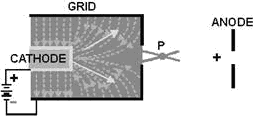
Figure 2-19. - Operation of the CRT grid. The proper name, BRIGHTNESS CONTROL, is given to the potentiometer used to vary the
potential applied to the control grid. The control grid actually serves as an electron lens. It is this electronic
lens that you adjust when you turn up the brightness control on your TV set. Notice that the effect of the grid is
to focus the electron beam at point P in figure 2-19. After passing point P, the electrons start to spread
out, or diverge, again. Therefore, it becomes necessary to provide some additional focusing to force the electrons
into a tight beam again. This is done by two additional positively-charged electrodes as shown in figure 2-20. The
first electrode is commonly called the FOCUSING ANODE. Generally, the focusing anode is charged a
few hundred volts positive with respect to the cathode. Electrons emitted by the cathode are attracted to the
focusing anode. This is the reason that they travel through the small hole in the grid. The second electrode,
called the
ACCELERATING ANODE, is charged several thousand volts positive in relation to the cathode. Any
electrons approaching the focusing anode will feel the larger electrostatic pull of the accelerating anode and
will be bent through the opening in the focusing anode and will travel into the area labeled D. You might think
that once an electron is in this region, it is simply attracted to the accelerating anode and that is the end of
it. This does not happen. Because the accelerating anode is cylindrical in shape, the electrostatic field
radiating from it is equal in all directions. Thus, an electron is pulled in all directions at once, forcing the
electron to travel down the center of the tube. Then, the electron is accelerated into the accelerating anode.
Once it passes the mid-point (point E), it feels the electrostatic attraction from the front wall of the
accelerating anode, which causes it to move faster toward the front. Once the electron reaches point F, equal
electrostatic attraction on either side of the opening squeezes it through the small opening in the front of the
anode. From there, it is joined by millions of other electrons and travels in a tight beam until it strikes the
screen (point S).

Figure 2-20. - Electron-beam formation In a CRT.
2-20
| - |
Matter, Energy,
and Direct Current |
| - |
Alternating Current and Transformers |
| - |
Circuit Protection, Control, and Measurement |
| - |
Electrical Conductors, Wiring Techniques,
and Schematic Reading |
| - |
Generators and Motors |
| - |
Electronic Emission, Tubes, and Power Supplies |
| - |
Solid-State Devices and Power Supplies |
| - |
Amplifiers |
| - |
Wave-Generation and Wave-Shaping Circuits |
| - |
Wave Propagation, Transmission Lines, and
Antennas |
| - |
Microwave Principles |
| - |
Modulation Principles |
| - |
Introduction to Number Systems and Logic Circuits |
| - |
- Introduction to Microelectronics |
| - |
Principles of Synchros, Servos, and Gyros |
| - |
Introduction to Test Equipment |
| - |
Radio-Frequency Communications Principles |
| - |
Radar Principles |
| - |
The Technician's Handbook, Master Glossary |
| - |
Test Methods and Practices |
| - |
Introduction to Digital Computers |
| - |
Magnetic Recording |
| - |
Introduction to Fiber Optics |
| Note: Navy Electricity and Electronics Training
Series (NEETS) content is U.S. Navy property in the public domain. |
|


