Module 6 - Introduction to Electronic Emission, Tubes, and Power
Supplies
Pages i,
1-1,
1-11,
1-21,
1-31,
1-41,
1-51,
2-1,
2-11,
2-21,
2-31,
3-1,
3-11,
3-21,
3-31,
3-41,
3-51, AI-1, Index
The CRT SCREEN
The inside of the large end of a CRT is coated with a fluorescent material that gives off light when struck by
electrons. This coating is necessary because the electron beam itself is invisible. The material used to convert
the electrons'energy into visible light is a PHOSPHOR. Many different types of phosphor materials
are used to provide different colored displays and displays that have different lengths of PERSIsTENCE
(duration of display).
In one way, the CRT screen is similar to a tetrode vacuum tube. Both suffer from the effects of secondary
emission. In order to reach the screen, electrons from the cathode are accelerated to relatively high velocities.
When these electrons strike the screen, they dislodge other electrons from the material of the screen. If these
secondary emission electrons are allowed to accumulate, they will form a negatively-charged barrier between the
screen and the electron beam, causing a distorted image on the CRT screen. The method used to control secondary
emission, which you are already familiar with, i.e., a suppressor grid, is not practical in CRT's. Instead, a
special coating called an AQUADAG COATING is applied to the inside of the tube as shown in figure
2-21. This coating is composed of a conductive material, such as graphite, and has the same high-positive
potential applied to it that is applied to the accelerating anode. This allows the aquadag to perform two
functions. First, since the aquadag coating is positive, it attracts the secondary emitted electrons and removes
them. Second, because the aquadag is operated at a high-positive potential and is mounted in front of the
accelerating anode, it aids in the acceleration of electrons toward the screen.
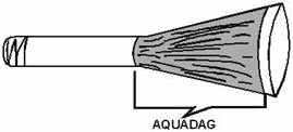
Figure 2-21. - Aquadag coating in a CRT. Before going on, let's review what you have already learned about CRT operation. 1. Electrons
are emitted from a specially constructed cathode and move toward the front of the CRT. 2. The number
of electrons that leave the area of the cathode is determined by the cap-shaped grid. In addition, the grid
concentrates the emitted electrons into a beam. 3. The electron beam is focused and accelerated toward
the screen by two electrodes: the focusing anode and the acceleration anode. 4. The electron beam
strikes the screen and causes a bright spot to appear at the point of impact. 5. Any electrons released
by secondary emission are removed from the tube by the aquadag coating.
2-21
DEFLECTION At this point, you have a bright spot in the center of the CRT
screen as shown in figure 2-22. Having watched TV, you know that a TV picture consists of more than just a bright
spot in the center of the picture tube. Obviously, something is necessary to produce the picture. That something
is called DEFLECTION. For the CRT to work properly, the spot must be moved to various positions
on the screen. In your TV set for example, the spot is moved horizontally across the CRT face to form a series of
tightly packed lines. As each line is displayed, or traced, the electron beam is moved vertically to trace the
next line as shown in figure 2-23. This process starts at the top of the tube and ends when the last line is
traced at the bottom of the CRT screen. Because the beam is swept very quickly across the CRT and the phosphor
continues to glow for a short time after the beam has moved on, you do not see a series of lines, but a continuous
picture.
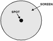
Figure 2-22. - Impact of an electron beam on a CRT screen.
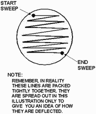
Figure 2-23. - Deflection of an electron beam across a TV screen.
2-22
These same principles also apply to the CRT used in your use of your major tool: the
OSCILLOSCOPE. Remember, the unique function of a CRT is to convert electronic (and electrical) signals to
a visual display. This function of a CRT is used in the oscilloscope to show the waveform of an electronic signal.
To help you understand better how an oscilloscope works, we will discuss the type of deflection used in
oscilloscopes. Bear in mind that the following discussion is only about deflection; we will cover the actual
operation of an oscilloscope in a later NEETS module that deals specifically with test equipment.
Electrostatic Deflection As you should know, there are two ways to move an electron (and
thus an electron beam): either with a magnetic or with an electrostatic field. Because of this, there are three
possible ways to move or deflect an electron beam in a CRT: magnetically, electromagnetically, and
electrostatically. All three ways are used in electronics. In general, though, electrostatic and electromagnetic
deflection are used most often. Your TV set, for example, uses electromagnetic deflection, while much of the test
equipment in the Navy uses electrostatic deflection. ELECTROSTATIC DEFLECTION uses
principles you are already familiar with. Namely, opposites attract, and likes repel. Look at figure 2-24, view A.
Here you see an electron traveling between two charged plates, H1 and H2. As you can see, before the electron
reaches the charged plates, called
DEFLECTION PLATES, its flight path is toward the center of the screen. In view B, the electron
has reached the area of the deflection plates and is attracted toward the positive plate, H2, while being repelled
from the negative plate, H1. As a result, the electron is deflected to the right on the inside of the screen. You,
the viewer, will see the spot of light on the left side of the CRT face (remember, you are on the opposite side
of the CRT screen). This is shown in view C.
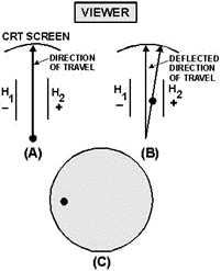
Figure 2-24. - Deflection in a CRT. A spot of light on the left-hand side of the CRT screen, however, is no more useful than a spot of light
in the center of the screen. To be useful, this spot will have to be converted to a bright line, called a sweep,
across the face of the CRT screen. We will explain the manner in which this is done by using
2-23
figure 2-25. In view A, five electrons are emitted in sequence, 1 through 5, by the electron gun. The right
deflection plate, H 2, has a large positive potential on it while the left plate, H1 has a large negative
potential on it. Thus, when electron 1 reaches the area of the deflection plates, it is attracted to the right
plate while being repelled from the left plate. In view B, electron 2 has reached the area of the deflection
plates. However, before it arrives, R1 and R2 are adjusted to make the right plate less positive and the left
plate less negative. Electron 2 will still be deflected to the right but not as much as electron 1. In view C,
electron 3 has reached the area of the deflection plates. Before it gets there, R1 and R2 are adjusted to the
mid-point. As a result, both plates have 0 volts applied to them. Electron 3 is not deflected and simply travels
to the center of the CRT screen. In view D, electron 4 has reached the area of the deflection plates. Notice that
R1 and R2 have been adjusted to make the right plate negative and the left plate positive. As a result, electron 4
will be deflected to the left. Finally, in view E, the left plate is at its maximum positive value. Electron 5
will be deflected to the extreme left. What you see when you are facing the CRT is a bright luminous line, as
shown in view E. While this description dealt with only five electrons, in reality the horizontal line across a
CRT face is composed of millions of electrons. Instead of seeing five bright spots in a line, you will see only a
solid bright line.

Figure 2-25. - Horizontal deflection.
2-24
In summary, the horizontal line displayed on a CRT or on the face of a television tube is made by
sweeping a stream of electrons rapidly across the face of the CRT. This sweeping action, or scanning, is performed
by rapidly varying the voltage potential on the deflection plates as the electron stream passes.
Vertical Deflection As we mentioned earlier, a CRT can be used to graphically and visually plot
an electronic signal, such as a sine wave. This is done by using a second set of deflection plates called
VERTICAL- DEFLECTION PLATES. Examine figure 2-26. You are looking at the front view (facing the screen)
of a CRT, back into the tube at the deflection plates. In normal usage, the horizontal plates sweep a straight
line of electrons across the screen from left to right while the signal to be displayed is applied to the vertical
deflection plates. a circuit of this type is shown in figure 2-27. We will use this figure to explain how a sine
wave is displayed. First, however, you need to understand what is happening in view A. The box on the left of the
CRT labeled HORIZONTAL-DEFLECTION Circuits is an electronic circuit that will duplicate the
actions of R1 and R2 used earlier in making up a horizontal line. How it works will be discussed in a later
NEETS module. Notice T1; the output of this transformer is applied to the vertical- deflection
plates. The signals applied to the vertical plates are 180º out of phase with each other. Thus, when one plate is
attracting the electron beam, the other will be repelling the electron beam. Because you are only concerned with
what happens inside the CRT, this circuitry will be eliminated and only the CRT and its deflection plates will be
shown, as in view B.
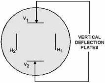
Figure 2-26. - Arrangement of deflection plates in a CRT, front view. 2-25
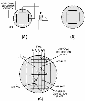
Figure 2-27. - Vertical deflection in a CRT. Now look at view C. While this illustration looks complicated, don't let it worry you. You have already
analyzed more complicated diagrams. The sine wave in the center of the screen is the signal that will be displayed
as a result of the two 180º out-of-phase sine waves applied to the vertical-deflection plates. The five spots on
the center sine wave represent the five electrons used to explain horizontal deflection. Only now these electrons
will be deflected both vertically and horizontally. Time lines T1 through T5 represent the time when each
like-numbered electron reaches the area of the deflection plates. Because you already know how the electron beam
is swept or deflected horizontally, we will not discuss horizontal deflection. Just remember that from T1 to T5,
the electron beam will be continuously moved from your left to your right. Now that you know where everything is
on the illustration, you are ready to discover how a sine wave is displayed on a CRT. At time 1 (T1), the
sine waves applied to both vertical-deflection plates are at their null points, or zero volts. As a result,
electron 1 is not vertically deflected and strikes the CRT at its vertical center. At time 2 (T2), the sine wave
applied to the top plate is at its maximum negative value. This repels electron 2 toward the bottom of the CRT. At
the same time, the sine wave applied to the bottom plate is at the most positive value, causing electron 2 to be
attracted even further toward the bottom of the CRT. Remember, the beam is also being moved to the left. As a
result, electron 2 strikes the CRT face to the right of and below electron 1. At time 3 (T3), both sine waves
applied to the vertical-deflection plates are again at the null point, or zero volts. Therefore, there is no
vertical deflection and electron 3 strikes the CRT face in
2-26
the center of the vertical axis. Because the electron beam is still moving horizontally, electron 3
will appear to the right of and above electron 2. At time 4 (T4), the sine wave applied to the top vertical-
deflection plate is at its maximum positive value. This attracts electron 4 toward the top deflection plate. The
upward deflection of electron 4 is increased by the negative-going sine wave (at time 4) applied to the bottom
deflection plate. This negative voltage repels electron 4 upward. Thus, electron 4 strikes the CRT face to the
right of and above electron 3. Finally, at time 5 (T5) both input sine waves are again at zero volts. As a result,
electron 5 is not deflected vertically, only horizontally. (Remember, the beam is continually moving from right to
left.) While this discussion is only concerned with five electrons, vertical scanning, or deflection,
involves millions of electrons in a continuous electron beam. Instead of seeing five spots on the CRT screen, you
will actually see a visual presentation of the sine wave input. This was, as you remember, described earlier as
the unique feature of the CRT. You may have wondered why so much space in this chapter was taken up with the
discussion of the CRT. There are two reasons for this. First, the field of electronics is in a constant state of
evolution. Transistors replaced most vacuum tubes. Transistors are being replaced by integrated circuits (ICs). As
you progress in your career in electronics, you will find that the equipment you work on will follow this
evolution, from transistors to IC chips. Of all the tubes discussed in this text, the CRT is the least likely to
be replaced in the near future. Thus, in all probability, whether your career in electronics lasts for only the
time you spend with this text or 20 years, the CRT will be your constant companion and co-worker. The
second reason for this rather extensive coverage of the CRT is that, while the CRT has a unique ability, it
operates exactly like all the tubes previously discussed. Summary of The CRT This
summary will not only review the CRT, but will also point out the similarities between the CRT and other tubes.
Look at figure 2-28. Here you see both a schematic diagram and a pictorial representation of a CRT. Each
element is identified by a circuit number. We will review briefly the function of each element in a CRT and its
similarity to elements in conventional tubes. This summary will help you tie together everything you have learned
about the CRT and electron tubes in general.
2-27
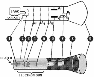
Figure 2-28. - Summary of the CRT. 1. The Heater - serves as the source of heat for the cathode in both the
CRT and indirectly heated tubes. 2. The Cathode - serves as the source of
thermionically emitted electrons in both the CRT and conventional tubes. The major difference is that in the CRT,
the cathode is circular in shape and the outer surface is coated to ensure that electron emission is roughly
unidirectional. 3. The Control Grid-in both the CRT and conventional
vacuum tubes, the control grid controls the number of electrons that will be fired across "the gap." The major
difference is in the physical construction. Conventional tubes use a wire-mesh ladder-type grid, while the CRT uses a cap- like grid. 4. The Focusing Anode - in the CRT, this anode serves
a dual purpose of attracting electrons from the area of the control grid and focusing the electrons into a beam.
Its function of attracting electrons from the area of the grid is similar to the action of the plate in a
conventional tube. The focusing action of the anode is similar to that performed by beam-forming plates in the
beam- forming tetrode. Bear in mind, though, that beam-forming plates are negatively charged and repel electrons
into electron sheets, while the focusing anode is positively charged and attracts electrons into beam.
5. The Accelerating Anode - in the CRT, this anode is used to accelerate the
electrons toward the front of the tube. Its action is similar to the screen grid of tetrodes and pentodes. But
remember, while the screen grid in conventional tubes accelerates electrons toward the plate, its primary purpose
is to reduce interelectrode capacitance, NOT accelerate electrons. 6.
The Vertical-Deflection Plates - in the CRT, these plates move the electron beam up and
down the screen. The input signal is usually applied to these plates. While no equivalent element is
2-28
found in conventional tubes, the principle employed (electrostatic attraction and repulsion) forms the
heart of all vacuum tube operation. 7. The Horizontal-Deflection Plates - in
the CRT, these plates move the electron beam by electrostatic attraction and repulsion, horizontally across the
CRT screen. In most equipment using the CRT, including television sets, electronic signals are supplied to these
plates to trace or paint a horizontal line. 8. The Aquadag Coating - in the
CRT, this coating performs the same function as the suppressor grid in conventional tubes; namely, eliminating the
effects of secondary emission. In conventional tubes, the suppressor grid is negatively charged and repels
secondary emission electrons back to the plate. In the CRT, the aquadag is positively charged and attracts
secondary emission away from the screen. 9. The Screen - also called the
face, is a unique element of the CRT. When struck by electrons, the phosphor coating becomes luminous, or glows,
thus enabling the tube to visually present electronic signals. From this comparison of the CRT and other
types of electron tubes, one fact should be clear. Almost all tubes, no matter what their function, operate on two
principles: electrostatic attraction and repulsion, and thermionic emission. By keeping these two principles in
mind, you should be able to analyze any type of tube operation. Q14. What is the unique ability of the
CRT? Q15. What are the three main parts of CRT? Q16. What term is used for the ability of a
spot on a CRT screen to continue to glow after the electron bean has struck it and moved away? Q17. The
electron beam in a CRT is made to sweep from left to right across the screen. What tube element causes this
sweeping motion? Q18. In applications where electronic waveforms are displayed on a CRT screen, the
input signal is normally applied to what CRT element?
Safety There are certain safety precautions you should follow when you work with or handle the special tubes
covered in this chapter. We will examine these tubes and their associated precautions in the following sections.
ELECTRON TUBES The average electron tube is a rugged device capable of withstanding the
shocks and knocks of everyday usage and handling. However, they are not indestructible. You should remember that
most electron tubes contain a near vacuum enclosed by a glass envelope. Because of this, the glass is under
constant stress from atmospheric pressure. Any undue stress, such as striking the envelope against a hard surface,
may cause the envelope to shatter, resulting in an IMPLOSION. An implosion is just the
opposite of an explosion. When the glass envelope of an electron tube shatters, the outside atmosphere rushes into
the tube to fill the vacuum. As the air rushes into the tube, it
2-29
carries glass fragments of the envelope with it. Once these fragments reach the center of the tube,
they continue outward with considerable velocity. The result is similar to an explosion, in that the immediate
area surrounding the electron tube is filled with fast-moving glass fragments. You, as a nearby object, may find
yourself the target for many of these glass fragments. For this reason you should handle all
electron tubes with care. CATHODE-RAY TUBES (CRTS) Since most electron
tubes are small, the possibility of them being a safety hazard is usually very small. There are two exceptions to
this: CRT's and radioactive tubes. The glass envelope of a CRT encloses a high vacuum. Because of its
large volume and surface area, the force exerted on a CRT by atmospheric pressure is considerable. The total force
on a 10-inch CRT may exceed 4,000 pounds. Over 1000 pounds is exerted on the CRT face alone. When a CRT is
broken, a large implosion usually occurs. Almost two tons of force hurl glass fragments toward the center of the
tube. At the same time, the electron gun is normally thrown forward inside the tube. The face, because of its
size, tends to move very slowly toward the center of the tube. This presents one of the main hazards of a broken
CRT. The electron gun passes through the center of the tube with considerable force. It continues until it strikes
the CRT face. The impact from the electron gun normally breaks the CRT face into many small fragments, which are
hurled outward. The face is coated with a chemical coating that is extremely toxic. If you are unfortunate enough
to experience an accidental implosion of a CRT and are nicked by one of these fragments, seek immediate medical
aid. As you can see, improper handling of a CRT can be very hazardous to your health. The CRT is, in
essence, a tiny fragmentation bomb. The major difference between a CRT and a bomb is that a bomb is designed to
explode; a CRT is not. As long as you handle a CRT properly, it represents no danger to you. Only when you
mishandle it do you risk the danger of being pelted with an electron gun and toxic glass fragments. When handling
a CRT, you should take the following precautions: 1. Avoid scratching or striking the surface of the
CRT. 2. Do not use excessive force when you remove or replace a CRT's deflection yoke or socket.
3. Do not try to remove an electromagnetic-type CRT from its yoke until you have discharged the high voltage
from the CRT's anode connector (hole). 4. Never hold the CRT by its neck. 5. Always set the
CRT with its face down on a thick piece of felt, rubber, or smooth cloth. 6. Always handle the CRT
gently. Rough handling or a sharp blow on the service bench can displace the electrodes within the tube, causing
faulty operation. 7. Wear safety glasses and protective gloves.
One additional handling procedure you should be aware of is how to dispose of a CRT properly. When you replace a
CRT, you cannot simply throw the old CRT over the side of the ship, or place it in the nearest dumpster. When
thrown over the side of a ship, a CRT will float; if it washes ashore, it is dangerous to persons who may come in
contact with it. a CRT thrown in a dumpster represents a hidden booby trap. Therefore, always render the CRT
harmless before you dispose of it. This is a fairly simple procedure, as outlined below. Note: Be sure to
wear safety goggles.
2-30
| - |
Matter, Energy,
and Direct Current |
| - |
Alternating Current and Transformers |
| - |
Circuit Protection, Control, and Measurement |
| - |
Electrical Conductors, Wiring Techniques,
and Schematic Reading |
| - |
Generators and Motors |
| - |
Electronic Emission, Tubes, and Power Supplies |
| - |
Solid-State Devices and Power Supplies |
| - |
Amplifiers |
| - |
Wave-Generation and Wave-Shaping Circuits |
| - |
Wave Propagation, Transmission Lines, and
Antennas |
| - |
Microwave Principles |
| - |
Modulation Principles |
| - |
Introduction to Number Systems and Logic Circuits |
| - |
- Introduction to Microelectronics |
| - |
Principles of Synchros, Servos, and Gyros |
| - |
Introduction to Test Equipment |
| - |
Radio-Frequency Communications Principles |
| - |
Radar Principles |
| - |
The Technician's Handbook, Master Glossary |
| - |
Test Methods and Practices |
| - |
Introduction to Digital Computers |
| - |
Magnetic Recording |
| - |
Introduction to Fiber Optics |
| Note: Navy Electricity and Electronics Training
Series (NEETS) content is U.S. Navy property in the public domain. |
|


