|
|||||||||||||
 |
|||||||||||||
Modern Radio Practice in Using Graphs and Charts - Part 7 |
|||||||||||||
I've always disliked book and article titles containing the word "Modern" because the word is utterly ambiguous and usually downright misleading more than a few years past the original publication date. What at publication time was modern is usually obsolete merely a decade later, especially in the realm of high technology. Sometimes, however, as with this 1932 Radio News magazine article on insulation (dielectric) breakdown voltages, bringing the information up to date requires only the addition of an extra couple decimal points of precision and/or the substitution of a few words. For instance, replace "condenser" with "capacitor" and units of "mfd" with "μF" and "mmfd" with "pF." Then you'll be on your way to gaining useful information. You might not find some of the dielectric types pertinent today, like gutta percha, which is what covered the world's first transatlantic submerged communications cables. There is a nice nomograph for use in designing capacitors for specific voltage handling and a table of dielectric puncturing voltages as well. Orion Instruments has a very extensive table of dielectric constant values. Modern Radio Practice in Using Graphs and Charts - Part 7
Figure 2 - Table of break-down voltages for various types of sheet insulation (dielectric strength). By John M. Borst Part Seven Calculations in radio design work usually can be reduced to formulas represented as charts which permit the solution of mathematical problems without mental effort. This series of articles presents a number of useful charts and explains how others can be made The capacity of a homemade condenser is often more or less of a mystery. The amateur or experimenter who does not possess a bridge or capacity standard must calculate the capacity. Conversely, if a condenser of a given capacity is desired, only a calculation will eliminate guesswork. The standard formula has been transformed into an alignment chart in Figure 1. The capacity of a condenser can be found when the area of the plates, their number, distance and the kind of dielectric are known. The relation between centimeters and inches or mils as well as the relation between square centimeters and square inches, centimeters and microfarads is also shown in Figure 1. The "dielectric constant," also called "inductivity" or "specific inductive capacity," is incorporated on the chart, which makes the consultation of any sources superfluous. The formula for the capacity of a condenser consisting of parallel plates is
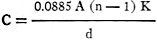
where A = the area of one plate in square centimeters d = the distance between two plates in centimeters n = the number of plates K = the specific inductive capacity This expression refers to a condenser with alternate plates in parallel. The formula does not take into consideration the spreading of the lines of force at the edges of the plates. This effect is negligible so long as the thickness of the dielectric is small compared to the area of the plates. In designing this chart the prime idea has been to cover all possible cases which occur in practice. Therefore, the capacity scale ranges from 1 micro-microfarad to over 10 micro-farads, and the other quantities also cover a wide range. Examples
A Chart (Nomograph) That Works For You Figure 1 - The size of condenser plates their distance apart, the number of plates, kind of dielectric or capacity can be found from this chart if the other four quantities are known. The five quantities are on three straight lines as shown in the example above. Two metal plates have an area of 1 square inch and are placed parallel, 1/4 inch apart, in air. What is the capacity? Referring to the chart, draw a line from the 1-square-inch mark on the "Area" scale to 1 on the K scale. The specific inductive capacity of air is one (unity). This gives you an intersection on the turning scale No. 1. From this newly found point draw another line through the point 2 on the N scale and find a second point on the turning scale No.2. The final line is drawn through the latter point and the 250-mils mark on the d scale. This line intersects the capacity scale at 0.9 mmfd. When exactly 1 mmfd. is required, the last line should be turned around its point on the turning scale No. 2 until it intersects the capacity scale at the 1 mmfd. mark and the intersection on the d scale shows the required distance between the plates (225 mils). The distance, however, can be left the same and the problem worked backwards, in which case an area of 1.1 square inch is found necessary. These lines have not been added in Figure 1 because they are so close together that it might confuse the reader. When using these charts. needless to say, one should not actually draw the lines but use a transparent ruler, a regular ruler or a tight thread. The second example shows how to work the problem backward. Suppose a paper condenser of 1 mfd. is wanted and the dielectric available has a thickness of 2 mils. This is manila paper, treated with paraffin. Its specific inductive capacity is 3.65 and the break-down voltage may run as high as 250 volts per mil. There is one more quantity which can be chosen and then the other one is determined. This can be either the number of plates or the size of the plates. The number of plates is the best to assume, because this has to be a whole number. Let us assume there shall be 30 plates. For the solution of this problem, start at the 1 mfd. mark on the capacity scale. A line from this point to the 2 mil. mark on the d scale intersects the turning scale No. 2. Draw a line through the latter point and through the point representing the number of plates (30). Now note the intersection on the turning scale No. 1. Finally draw the last line from the point representing the dielectric constant. 3.65, through the point on the turning scale No.2, which shows the necessary area of the plates as 84 square inches. As a check-up, an actual calculation gave the area as 83.7 square inches. The experience of this second example teaches us that in certain cases the last line would intersect the area scale beyond the limits of the paper. This means that the area of the plates needed is going to be larger than 100 square inches. If the area is to be smaller than 100 square inches, either the number of plates have to be increased, the thickness of the dielectric decreased or the material exchanged for one with a greater inductivity. Then try again. If one wishes the problem solved for values of variables outside the range of the chart, then some multiplying stunt has to be employed. For instance, suppose the paper in the above example had been dry paper with a dielectric constant of 1.8, then the last line does not intersect the area scale within the limits of the page. Therefore, multiplying 1.8 with any convenient number - say, 5 - the last line is drawn from 9 through the intersection on the turning scale number one and the area scale is intersected at 34. This result must now be multiplied by five in order to find the correct answer, which is 170 square inches. While determining the specifications for a condenser it is important to be sure that the dielectric will stand the applied voltage. Therefore a list of the break-down voltages for different materials is found in Figure 2. Capacity of a Condenser (aka Capacitor) Temperature influences the ability of a dielectric to withstand electric pressure. When the condenser heats up under a continuous load, the breakdown voltage is lowered. Therefore the tests of such condensers must be made over a considerable time at working voltage or at a much higher voltage for a short time. Commercial paper condensers usually consist of long strips of prepared paper, with tinfoil interleaved, which is then rolled. In the case of rolling a condenser with an even number of plates, the top plate and the bottom plate form an additional section of the condenser so that in this case the rolling has the effect of adding one more plate. The reader should see whether the dielectric for this additional section has the same thickness as the other sections and make allowances for any possible difference. When the number of plates is odd or when the paper is not rolled, the actual number of plates is used for the calculation. The accuracy of a calculation by means of this chart will be sufficient only if the correct values for the dielectric constant and the thickness of the dielectric have been determined. This is sometimes difficult to accomplish, especially with paper as a dielectric. If the reader guesses at the constant and the actual separation of the plates, he must expect the result to be off accordingly.
Nomographs / Nomograms Available on RF Cafe: - Parallel Series Resistance Calculator - Transformer Turns Ratio Nomogram - Symmetrical T and H Attenuator Nomograph - Voltage and Power Level Nomograph - Nomogram Construction for Charts with Complicating Factors or Constants - Voltage, Current, Resistance, and Power Nomograph - Resistance and Capacitance Nomograph - Voltage, Power, and Decibel Nomograph - Resistance and Reactance Nomograph - Frequency / Reactance Nomograph
Posted December 29, 2021 |
|||||||||||||
 |
|||||||||||||
|
|||||||||||||


 in
micro-microfarads
in
micro-microfarads 

|
||||||||||||||||||||||||||||||||||||


