| - |
Matter, Energy,
and Direct Current |
| - |
Alternating Current and Transformers |
| - |
Circuit Protection, Control, and Measurement |
| - |
Electrical Conductors, Wiring Techniques,
and Schematic Reading |
| - |
Generators and Motors |
| - |
Electronic Emission, Tubes, and Power Supplies |
| - |
Solid-State Devices and Power Supplies |
| - |
Amplifiers |
| - |
Wave-Generation and Wave-Shaping Circuits |
| - |
Wave Propagation, Transmission Lines, and
Antennas |
| - |
Microwave Principles |
| - |
Modulation Principles |
| - |
Introduction to Number Systems and Logic Circuits |
| - |
- Introduction to Microelectronics |
| - |
Principles of Synchros, Servos, and Gyros |
| - |
Introduction to Test Equipment |
| - |
Radio-Frequency Communications Principles |
| - |
Radar Principles |
| - |
The Technician's Handbook, Master Glossary |
| - |
Test Methods and Practices |
| - |
Introduction to Digital Computers |
| - |
Magnetic Recording |
| - |
Introduction to Fiber Optics |
| Note: Navy Electricity and Electronics Training
Series (NEETS) content is U.S. Navy property in the public domain. |
NEETS Module 17 - Radio-Frequency Communications Principles
Pages i,
1-1,
1-11,
2-1,
2-11,
2-21,
2-31,
3-1,
3-11,
3-21,
3-31,
3-41,
4-1- to 4-10,
4-11,
5-1,
5-11, Index

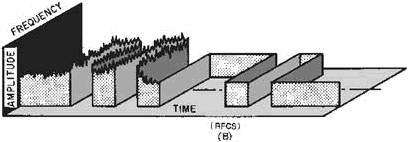
Figure 3-20A. - CW compared to an RFCS teletypewriter signal.

Figure 3-20B. - CW compared to an RFCS teletypewriter signal.
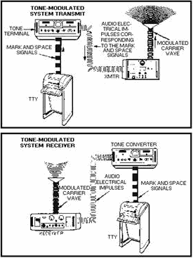
Audio Frequency TONE SHIFT. - Tone-modulated (AFTS) systems use amplitude modulation to change dc mark and space impulses into audio electrical
impulses.
A basic tone-modulated system is shown in figure 3-21. Conversion to audio tones
is accomplished by an audio oscillator in the tone converter. Rapid varying of the
tone, according to the characters transmitted from the teletypewriter equipment,
amplitude modulates the carrier wave in the transmitter. The receiver receives the
modulated signal and separates the audio signal from the carrier. This process of
separating the modulated signal is known as detection or demodulation.
3-21

Figure 3-21. - Basic tone modulated (AFTS) system.
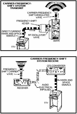
Radio-Frequency-CARRIER SHIFT. - For frequency-shift (FSK) systems,
the transmitter provides a source of radio-frequency excitation. Figure 3-22 illustrates
a basic frequency-shift keyed system. In modern systems, the keyer is built into
the transmitter. The keyer shifts the signal box below or above the assigned frequency
to correspond with the mark or space required to transmit TTY characters. Normally
the keyer is adjusted for an 850-hertz spread, 425 hertz above and 425 hertz below
the assigned frequency. a spacing impulse will be 425 hertz above the operating
frequency, and a marking impulse will appear 425 hertz below.
3-22

Figure 3-22. - Basic radio-frequency-carrier shift system (RFCS).
In both the tone-modulated system and the carrier-frequency shift system, all
TTY signals pass through the TTY panel that controls the looping current in all
the circuits. Looping current is the current supplied by the TTY battery. The TTY
panel integrates the tone-modulated and the carrier-frequency shift systems. It
provides every possible interconnection of available TTY equipment. With this configuration
maximum operational flexibility is achieved with the least amount of circuitry and
equipment.
Q19. What is the function of a keyer?
Q20. What is the function of a converter?
Q21. Basically describe an AFTS system.
Q22. Basically describe an RFCS system.
RFCS Send System
Figure 3-23 shows an RFCS teletypewriter transmit communications system. You
should refer to this figure frequently while reading the functional descriptions
of the equipment shown.
3-23

Figure 3-23. - RFCS transmit (send) system.
TELETYPEWRITER SETS. - Most of the teletypewriter sets used
by the Navy belong to one family of TTY equipment. This equipment features various
weights and sizes, quiet operation, and high operating speeds. They present relatively
few maintenance problems. Because of this they are well suited for severe shipboard
conditions of roll, vibration, and shock.
These teletypewriters operate at various speeds. Conversion from one speed to
another is usually only a matter of changing the gears that are located within the
equipment.
Teletypewriters may be send/receive units or receive only units. They may be
designed as floor models, table models, or rack and wall-mounted sets. The teletypewriter
shown is a send/receive floor model.
The teletypewriter receives messages and prints them on page-size copy paper.
In addition, it can receive and record messages on perforated tape. You can use
the keyboard or perforated tape to send messages. Page print monitoring is available
with both methods. The set shown can prepare perforated and printed tape for separate
transmission. It does this with or without simultaneous transmission and page-print
monitoring. The combinations of services available are extensive.
The TTY set may include a CABINET, KEYBOARD, Page PRINTER, TYPING PERforATOR,
Transmitter DIsTRIBUTOR, TYPING REPERforATOR, power distribution panels, and a power
supply.
In operation, the components are linked by electrical or mechanical connections.
You are given a wide range of possibilities for sending, receiving, or storing TTY
messages. All equipment components are housed within the cabinet. Transmission signals
are initiated through the keyboard (kybd) or through the
3-24
transmitter distributor (td). Signals received or local transmissions can be
monitored on the page printer. The typing perforator and typing reperforator are
devices for preparing tapes on which locally initiated or incoming TTY messages
can be stored for future transmission through the td.
Communication PATCHING PANELS. - TTYs are provided flexibility
by jacks that are used to terminate all TTYs and associated equipment. The jacks
are wired in communications patching panels, usually referred to as TTY patch panels.
You are able to connect any combination of equipment electrically by means of patch
cords.
The plugs on the patch cords are inserted into the jacks at the front of the
panel. These plugs have three different parts. They are the tip, ring, and sleeve.
The tip carries the intelligence signal while the ring carries the synchronizing
(step) or timing signals. The sleeve carries an alarm signal that indicates (both
visually and audibly) a problem to the operator. The problem may be equipment failure,
loss of loop current, or improper patching. Commonly used combinations of equipment
are often wired together within the panel (called normal-through). Individual pieces
of equipment are wired on jacks to allow you to use them alone or in combination.
TTY patch panels also furnish a central point for connecting the dc voltage supply
into the TTY circuits. One source of supply can be used for all circuits passing
through a particular panel.
RED and BLACK are used on patch panels to identify whether that panel is used
for passing secure or nonsecure information. Red indicates that secure (encrypted)
information is being passed through the panel. Black indicates that nonsecure (unencrypted)
information is being passed. Patch panels through which secure information is passed
are indicated by a red sign on the front that has inch high white block letters
that say "RED PATCH PANEL." Panels through which nonsecure information is passed
are indicated by two black signs on the front with inch high white block letters.
One sign says "BLACK PATCH PANEL" and the other "UNCLAS ONLY."
Each panel contains six channels. Each channel has its own series circuit of
looping jacks, set jacks, and a rheostat for adjusting line current. The number
of looping and set jacks in each channel varies with the panel model. Each panel
includes a meter and rotary selector switch for measuring the line current in any
channel. There are six miscellaneous jacks. Any TTY equipment not regularly assigned
to a channel, may be connected to one of these jacks.
If the desired TTY equipment is wired in the same looping channel as the radio
adapter used, no patching is required. But, if the desired TTY is not wired in the
same looping channel as the keyer or converter, it must be patched. For example,
let's put a TTY on channel 1 and a converter on channel 3. If you want to receive,
you must insert one end of the patch cord in the set jack for channel 1 and the
other end in either one of the two looping jacks of channel 3.
In any switching operation between the plugs and jacks of a TTY panel, the cord
plug must be pulled from the looping jack before you remove the other plug from
the set (machine) jack. Pulling the plug from the set jack first opens the circuits
to the channel, causing all TTY messages in the channel to be interrupted.
Warning
Removing the set (machine) jack before the looping jack exposes a dangerous
dc voltage on the exposed plug.
Q23. Most Navy TTY sets operate at what speeds?
Q24. a receive TTY set provides outputs in what formats?
3-25
Q25. What does the color red indicate on a TTY patch panel?
CRYPTOGRAPHIC Equipment. - Cryptographic equipment is used to
ENCRYPT and DECRYPT TTY messages that require security handling. (Encrypting is
the method used to code a transmitted message; decrypting is used to decode a received
message.) To code or decode any message, the send and receive cryptographic equipment
must be compatible.
REMOTE Transmitter CONTROL UNIT. - The remote transmitter-control
unit is mounted close to the KYBD and permits remote control of the transmitter
(XMTR). It has a transmitter power on-off switch, a power-on indicator lamp, a carrier-on
indicator lamp, and a three-position rotary selector switch. For RFCS operation
you set the switch to CFS SEND to transmit and to CFS REC to receive. use the TONE
S/R position for both transmitting and receiving AFTS signals.
An audio frequency tone-shift system will be discussed later in this chapter.
Transmitter Transfer SwitchBOARD. - The transmitter transfer
switchboard is used in this system to connect the remote transmitter control unit
to the radio transmitter.
Radio Transmitter. - The radio transmitter transmits the TTY
signal. You should be careful when tuning the transmitter for RFCS operation. The
carrier frequency setting is critical and must be properly set to ensure a correct
output from the transmitter.
Q26. What are the functions of cryptographic equipment?
RFCS Receive System
Figure 3-24 shows the RFCS receive system used to receive the transmitted signal
and translate it back to a usable output. You should look at this figure while studying
the units in this section.
3-26

Figure 3-24. - RFCS receive system.
Antenna FILTER ASSEMBLY. - The antenna filter assembly is connected
to the antenna and receives the RF signal from the antenna. It filters out any unwanted
RF signals and allows the desired band of frequencies to pass.
Radio RECEIVER. - The radio receiver takes the RF signal passed
on by the antenna filter and translates it to an audio signal.
RECEIVER Transfer SwitchBOARD. - The receiver transfer switchboard
is used to tie the receiver to any converter unit connected to it. This allows you
a wide selection of equipment for connection to the same receiver.
CONVERTER-COMPARATOR GROUP. - The converter-comparator group
is used with receivers in either space or frequency diversity operation. When diversity
operation is not required, each converter can be used separately with a single receiver.
Each converter has its own COMPARATOR circuitry. This built-in design feature
results in a considerable reduction in size from older units. The comparator was
located in a separate chassis in the older units. Size has been further reduced
through the use of microelectronics.
Figure 3-25 shows the basic method we use to convert a frequency-shift RF signal
into a signal that controls the dc loop of a TTY. The frequency shifts of the AF
output from the receiver are converted into dc pulses by the AF discriminator. The
dc pulses are then fed into the keyer. The keyer opens and closes the dc loop of
the TTY according to the mark and space characters received.
3-27

Figure 3-25. - Frequency shift receiving system simplified block diagram.
In diversity operation the comparator section of the converter-comparator group
(shown in figure 3- 24) compares the strength of the signals from two receivers.
Signals from each converter are fed into a comparator circuit that compares the
signals. This comparison is displayed on a CRT on the front of the equipment. The
comparison is in the form of LIsSAJOUS Patterns. a lissajous pattern is a combined,
simultaneous display of the amplitude and phase relationships of two input signals.
One signal is applied to the vertical and the other to the horizontal deflection
circuits. Lissajous patterns have many applications in electronics. They have operational uses as well as uses in corrective and preventive maintenance. Further coverage
on lissajous patterns can be found in NEETS, Module 19, The Technician's Handbook.
Figure 3-26 shows several typical lissajous monitoring patterns for the converter-
comparator group. Once we have a correctly tuned signal, the comparator feeds it
to the communication patching panel for patching to the TTY. Now let's refer back
to figure 3-24 while we discuss the rest of the units in the system.

Figure 3-26. - Typical lissajous monitoring patterns.
Communication PATCH PANEL. - The communication patch panel serves
the same functions on the receive side of the RFCS system as it did on the transmit
side. It routes the dc signal to the
3-28
proper cryptographic equipment. It also routes the decoded teletypewriter signal
from the cryptographic equipment to the selected TTY.
CRYPTOGRAPHIC Equipment. - The cryptographic equipment converts
the transmitted coded signal to a decoded signal that can be printed out in its
original state.
TELETYPEWRITER. - The TTY equipment is used to convert the dc
signal received from the communication patch panel to a printed copy of the original
transmitted message. The TTY shown is used only for receive and does not have the
ability to transmit.
Q27. What are the functions of a converter-comparator group?
AFTS System
Figure 3-27 is a simplified block diagram of a Half-DUPLEX (send or receive)
uhf, audio- frequency-tone shift system. a half-duplex communications circuit permits
two-way communications between stations. Communications can be in either direction
but not simultaneously. The term half-duplex is qualified by adding send only, receive
only, or send or receive. Let's use the block diagram to trace a signal through
the system.

Figure 3-27. - Half-duplex AFTS teletypewriter system.
Signal FLow. - On the transmit side, dc signals from the TTY
set are fed to the communication patching panel. From the panel they are patched
to the tone terminal set. The tone terminal set converts
3-29
the dc signals into audio tone-shift signals. These signals are then patched
to the transmitter section of the transceiver through the transmitter transfer switchboard.
The audio tone-shift signals modulate the RF carrier generated by the transmitter
(XMTR). The RF tone-modulated signals are then radiated by the antenna.
On the receive side, the RF tone-modulated signals are received at the antenna.
You then patch the signal via the multicoupler to the receiver section of the transceiver.
Demodulation takes place at this point. The resulting audio tone-shift signals are
then patched through the receiver transfer switchboard. The signals now go from
the switchboard to the tone terminal set, where they are converted back to dc signals.
The dc signals are then patched through the communication patching panel to the
TTY for printing.
TONE TERMINAL SET. - In tone modulation transmission, the TTY
pulses are converted into corresponding audio tones. These tones amplitude modulate
the RF carrier in the transmitter. Conversion to audio tones is accomplished by
an audio oscillator in the tone converter.
An internal relay in the tone converter closes the control line to the transmitter.
This keys the transmitter on the air when the operator begins typing a message.
The transmitter remains keyed until after the message has been transmitted.
On the receive side, the tone converter accepts the mark and space tones coming
in from a receiver and converts them into signals suitable to operate a relay in
the converter. The make and break contacts of the relay are connected in the local
TTY dc loop circuit. This causes the teletypewriter to print in unison with the
mark and space signals from the distant TTY.
Multiplexing Equipment
The number of communications networks in operation throughout any given area
is increasing. As a result, all areas of the RF spectrum have become highly congested.
The maximum number of intelligible transmissions taking place in the radio spectrum
is being increased through the use of MULTIPLEXING. Multiplexing is the simultaneous
transmission of a number of intelligible signals (messages) in either or both directions
using only a single RF carrier. You may use two methods of multiplexing. These are
TIME-DIVIsION and Frequency-DIVIsION.
TIME-DIVIsION. - With AM voice and tone communications, we want
to transmit and receive for 360 degrees of each sine wave. However, an audio signal
may be transmitted and received satisfactorily by periodically sampling the signal.
The sampling process yields a received signal like the one shown in figure 3-28.
There is no limit to the maximum number of samples that may be made, but you must
sample at least twice per cycle of audio to get satisfactory results. In practical
systems, 2.4 samples per cycle are usually taken. This concept of sampling forms
the basis for time-division multiplex (tdm) operation.
3-30
|


