| - |
Matter, Energy,
and Direct Current |
| - |
Alternating Current and Transformers |
| - |
Circuit Protection, Control, and Measurement |
| - |
Electrical Conductors, Wiring Techniques,
and Schematic Reading |
| - |
Generators and Motors |
| - |
Electronic Emission, Tubes, and Power Supplies |
| - |
Solid-State Devices and Power Supplies |
| - |
Amplifiers |
| - |
Wave-Generation and Wave-Shaping Circuits |
| - |
Wave Propagation, Transmission Lines, and
Antennas |
| - |
Microwave Principles |
| - |
Modulation Principles |
| - |
Introduction to Number Systems and Logic Circuits |
| - |
- Introduction to Microelectronics |
| - |
Principles of Synchros, Servos, and Gyros |
| - |
Introduction to Test Equipment |
| - |
Radio-Frequency Communications Principles |
| - |
Radar Principles |
| - |
The Technician's Handbook, Master Glossary |
| - |
Test Methods and Practices |
| - |
Introduction to Digital Computers |
| - |
Magnetic Recording |
| - |
Introduction to Fiber Optics |
| Note: Navy Electricity and Electronics Training
Series (NEETS) content is U.S. Navy property in the public domain. |
NEETS Module 17 - Radio-Frequency Communications Principles
Pages i,
1-1,
1-11,
2-1,
2-11,
2-21,
2-31,
3-1,
3-11,
3-21,
3-31,
3-41,
4-1- to 4-10,
4-11,
5-1,
5-11, Index
Chapter 1
Introduction to Radio-Frequency Communications
Learning Objectives
Learning objectives are stated at the beginning of each chapter. These learning
objectives serve as a preview of the information you are expected to learn in the
chapter. The comprehensive check questions are based on the objectives. By successfully
completing the OCC/ECC, you indicate that you have met the objectives and have learned
the information. The learning objectives are listed below.
Upon completion of this chapter, you will be able to:
1. Define electrical telecommunications.
2. Describe the use of radiotelegraph, radiotelephone, teletypewriter,
and facsimile.
3. Define and describe the interrelationships of the system, set,
group, unit, assembly, subassembly, part, and reference designations.
4. State the frequency ranges of the various frequency bands and
describe the most common uses of those bands by the Navy.
5. Describe a strategic communications link.
6. Describe a tactical communications link.
7. Describe the five basic communications modes of operation.
8. Describe a switched communications network.
9. Describe the purpose of the two Navy-only networks.
Introduction to Naval Telecommunications
When the wireless (radiotelegraph) was invented, the Navy saw a possible use
for it. It could be used for communications from shore stations to ships along the
coast. In 1899, the first official naval radio message was sent from ship to shore.
It only traveled a distance of 20 miles but that was a start. The next advance was
in 1916 when the Navy first used radiotelephone between ships. Three years later
the first airborne radio was used to communicate with a ground station. In the early
years, communications was not the best because of poor tuning techniques. Receivers
often did not pick up the signal. This problem was almost eliminated in 1931 when
the first superheterodyne receivers were installed in the fleet. In 1944, another
important event took place. The first successful radio teletypewriter transmissions
between ships were completed. The first successful use of radiophoto (facsimile)
occurred in 1945 with the transmission of the surrender document signing that ended
World War II. Naval communications has grown tremendously in size and complexity
since then.
The fleets of our modern Navy travel faster and are spread over greater areas
of ocean than any seagoing force of the past. Commanders and their subordinates
throughout the Department of the Navy use the facilities of naval communications
as a primary method of communicating.
Naval communications relies on top performance from all of its assigned personnel.
Reliable, secure, and timely transmission and receipt of information, based on wartime
requirements, is the ultimate goal.
Previous modules have discussed electronic components or circuitry in individual
units. In this chapter we will tie up some loose ends for you and discuss radio-frequency
communications.
We will cover the considerations involved in receiving or transmitting a radio-frequency
signal between two or more geographic locations. Let's start by defining telecommunications.
Telecommunications refers to communications over a distance and includes any
transmission, emission, or reception of signs, signals, writings, images, or sounds.
Intelligence produced by visual means, oral means, wire, radio, or other electromagnetic
systems are also included. Electrical, visual, and sound telecommunications are
all used in the Navy. In this chapter we will talk only about electrical types of
telecommunications.
Electrical
The types of electrical communications are radio and wire. Radio uses electromagnetic
waves to transmit and receive intelligence. The waves are not guided by a physical
path between sender and receiver. Wire uses conductors to carry these waves. Radio
is the most important method the Navy has of communicating between widely separated
forces. The transmission methods we will be discussing are radiotelegraph, radiotelephone,
teletypewriter, and facsimile.
Radiotelegraph
Radiotelegraph transmissions are referred to as continuous wave (CW) telegraphy.
CW is a manual or automatic system of transmitting signals using a wave of radio-frequency
(RF) energy. The radio operator separates a continuously transmitted wave into dots
and dashes based on the Morse code. This is accomplished by opening and closing
a telegraphic hand key.
Radiotelegraphy was the first means of radio communications that had military
and commercial importance. Radiotelegraph still is used as a means of communication
to, from, and among widely separated units of the Navy.
Relative slow speed of transmission and the requirement for experienced operators
are the major disadvantages of radiotelegraph. The main advantage is reliability.
a thinking person at both sending and receiving stations provides a capability of
being understood not present in automated systems.
Radiotelephone
Radiotelephone is one of the most useful military communications methods. Because
of its directness, convenience, and ease of operation, radiotelephone is used by
ships, aircraft, and shore stations. It has many applications and is used for ship-to-shore,
shore-to-ship, ship-to-ship, air-to-ship, ship-to-air, air-to-ground, and ground-to-air
communications. Modern means of operation make it possible to communicate around
the world by radiotelephone. One of the most important uses of radiotelephone is
short-range tactical communications. This method permits tactical commanders to
communicate directly with other ships. Little delay results while a message is prepared
for transmission, and acknowledgments can be returned instantly. Radiotelephone
equipment for tactical use usually is operated on frequencies that are high enough
to have line-of-sight characteristics; that is, the waves do not
follow the curvature of the earth. As you know, these characteristics limit the
usual range of radiotelephone from 20 to 25 miles. This is important because it
reduces the chances of the enemy intercepting the message. Radiotelephone procedures
can be learned easily by persons with no other training in communications.
Radiotelephone has some disadvantages. You may find transmissions unreadable
because of static, enemy interference, or high local noise level caused by shouts,
gunfire, and bomb or shell bursts. Wave propagation characteristics of radiotelephone
frequencies sometimes are unpredictable, and tactical transmissions may be heard
from great distances. Most radiotelephone messages are in plain language, and if
information is to be kept from the enemy, users must keep their messages short,
stick to the proper procedures, and be careful of what they say.
Q1. What are the two types of electrical communications?
Q2. What is the main advantage of radiotelegraph communications?
Q3. Why is radiotelephone one of the most useful methods of military
communications?
Q4. What are the disadvantages of radiotelephone communications?
Teletypewriter
Teletypewriter (TTY) signals may be transmitted by either landline (wire), cable,
or radio. The landline TTY is used both by the military services and by commercial
communication companies. The Navy uses radio teletypewriter (RTTY) mainly for high-speed
automatic communications across ocean areas. The TTY unit is equipped with a keyboard
similar to a typewriter. When the operator presses a key, a sequence of signals
is transmitted. At receiving stations, the signals are fed into terminal equipment
that translates the sequences of signals into letters, figures, and symbols and
types the messages automatically.
The RTTY mode of transmission and reception is rapidly becoming more efficient
and reliable for communications between ships and from ship-to-shore. Ships copy
what is known as "fleet broadcast" messages on RTTY. The speed at which message
traffic is transmitted on RTTY circuits depends on the equipment in use. Normal
speed of operation is 100 words per minute, but it may be faster or slower. You
may find high-speed equipment, capable of printing a line or even a page at a time,
in some communications centers. The use of RTTY has brought about a considerable
savings in manpower.
Facsimile
Facsimile (fax) is the process used to transmit photographs, charts, and other
graphic information electronically. The image to be transmitted is scanned by a
photoelectric cell. Electrical changes in the cell output, corresponding to the
light and dark areas being scanned, are transmitted to the receiver. At the receiver,
the signal operates a recorder that reproduces the picture. The fax signals may
be transmitted either by landline or radio.
Facsimile transmissions suffer distortion from all of the common sources of interference
experienced with ordinary radiotelegraph and radio teletypewriter. Certain characteristics
of TIF transmission make it less susceptible to complete loss of intelligence. For
example, picture quality will be downgraded by any noise bursts, since facsimile
recording is a continuous recording of signals coming from a receiver. However,
because the machine scans material at the rate of about 100 lines per inch, each
line is only 1/100th of an inch high. So you can see, if a noise burst interferes
with the signal, it will distort a line only 1/100th of an inch high, leaving the
image still readable. Under similar circumstances on a conventional RTTY circuit,
such distortion could cause a portion of the page copy to be unreadable.
Facsimile transmission is not intended to be a replacement for teletypewriter
and other general methods of transmission. It is an important communications supplement
and provides a means of
handling certain types of graphic and pictorial intelligence by swift communications
methods. It is widely used by the Navy weather information services and ship and
station weather centers to obtain the latest
weather maps. Chances are the photo you saw in the newspaper was transmitted
by facsimile.
Q5. What is the main use of a radio teletypewriter?
Q6. What is facsimile?
System Introduction

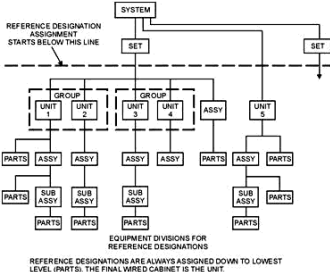
Figure 1-1 - System subdivision.
Until recently, Radio Communications brought to mind either telegraphy (CW),
voice (AM), or possibly radio teletypewriter (RTTY) communications. Today, radio
communications has become a highly sophisticated field of electronics. Even small
Navy ships have the capability to "come up" on the commonly used ship-to-ship, ship-to-air,
and ship-to-shore communications circuits. These circuit operations are accomplished
through the use of compatible and flexible communications systems.
A communications system (as you will see later in this chapter) consists of two
or more equipment sets (sets will be explained a little later). Communications systems
follow the system subdivision shown in figure 1-1. Systems are arranged and interconnected
to perform a circuit operation that cannot be performed by any single piece of equipment.
Navy communications systems vary from the simple to the very complex, depending
upon the circuit operations involved. Because a Navy ship must use every inch of
available space, the communications equipment may be spread over several portions
of the ship, for instance, receivers in one location, transmitters in another, and
terminal equipment in another. The equipment must be installed in such a manner
that it is flexible and can be used interchangeably with other installed communications
equipment. Consequently, large numbers of sets which make up the shipboard communications
system are installed and are capable of operating separately and simultaneously.
Flexibility is provided through a complex arrangement of interconnections. These
allow the physically separated equipment to be selectively switched (patched) by
you into different circuit configurations.
As naval electronics has grown in capability and complexity, an orderly plan
of equipment designations has been adopted. The largest designator, system, describes
equipment that work together for a specific function. For example, the radar system
of a ship includes every item of electronics equipment used in or with a radar on
board that ship. The smallest designator, part, describes one single piece, such
as a bolt or a resistor.
System

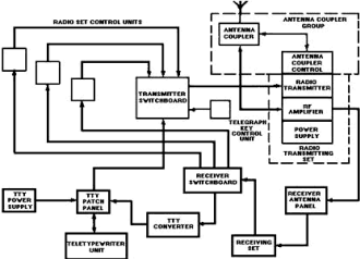
Figure 1-2 - Communications system pictorial view.

Figure 1-3 - Communications system block diagram. 
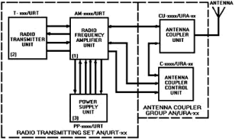
Figure 1-4 - Radio transmitting set.

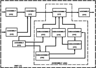
Figure 1-5 - Unit and assembly.
A System is a combination of sets, units, assemblies, subassemblies, and parts
joined together to perform a specific operational function or several functions.
Examples are communications systems, radar systems, or navigation systems. You will
find the majority of troubleshooting done in the Navy is system oriented. Figure
1-2 is a pictorial view of a typical communications system containing the components
necessary for transmission and reception of voice, telegraphy, and teletypewriter
signals. Figure 1-3 is a block diagram of the same communications system with the
arrows showing the direction of signal flow.
Set
A SET consists of a unit or units and the assemblies, subassemblies, and parts
connected or associated together to perform a specific function. a good example
of this is a radio receiving set or a radio transmitting set.
Figure 1-4 is a block diagram of a radio transmitting set. It consists of a radio-frequency
amplifier unit (1), a radio transmitter unit (2), a power supply unit (3), and an
antenna coupler group.
Group
A GROUP is a collection of units, assemblies, subassemblies, and parts. It is
a subdivision of a set or system, but it is not capable of performing a complete
operational function. The coupler requires power and signals from the radiofrequency
amplifier unit for operation. An example is the antenna coupler group in figure
1-4.
Unit
A UNIT is an assembly or any combination of parts, subassemblies, and assemblies
mounted together. a unit is normally capable of independent operation in a variety
of situations. An example of a unit might be a power supply.
Assembly
An ASSEMBLY is a number of parts or subassemblies, or any combination thereof,
joined together to perform a specific function. Figure 1-5 shows a unit (2) with
its six assemblies. The assembly (A6) contains six subassemblies.
Subassembly
A SUBASSEMBLY consists of two or more parts that form a portion of an assembly
or a unit. It is replaceable as a whole, but some of its parts are individually
replaceable.
The distinction between an assembly and a subassembly is not always exact; an
assembly in one application may be a subassembly in another when it forms a portion
of an assembly. Figure 1-6 shows a printed circuit board subassembly and some of
the parts which may be mounted on it.
Part
A PART is one component or two or more components joined together. a part is
not normally subject to disassembly without destruction. Resistors, capacitors,
and transistors are examples of parts.
Reference Designations.
Reference designations consist of letters, numbers, or both and are used for
identification purposes. Reference designations can be used in several different
ways. One important way you will use them is as a cross-reference for locating supply
stock numbers. When you know the reference designator, ordering the correct replacement
for a failed component is easy. You will also use them frequently in corrective
and preventive maintenance. Reference designators will help you to locate test points
and adjustments; they will also help you to move back and forth between various
technical manuals, schematics, tables, or other references.

Figure 1-6 - Typical subassembly.

Figure 1-7 - Reference designations.
Each set within a system is assigned an an nomenclature. Each unit, assembly,
subassembly, and part of a set has an assigned reference designation. Systems, sets,
and groups have no reference designation. The unit is the highest level assigned
a reference designator.
Each unit is assigned an identifying number. This number begins with the number
1 and runs consecutively for all units of a system or a set. Let's look back at
the radio transmitting set AN/URT-xx with the unit numbers 1, 2, 3 on figure 1-4.
You should note that these units may also have an an nomenclature, such as T-xxx/URT.
The T indicates the equipment is a transmitter. The xxx would be replaced by 3 digits
that indicate the model number.
By examining the reference designator of a unit, you will be able to determine
in which group, if any, the unit is contained. Let's look at a complete reference
designator for a unit. a good example for us to break down is the reference designator
2A2A3C1 on figure 1-7.
The first indicator, 2, is numeric and refers to unit 2. The next indicator,
A2, is alphanumeric and refers to assembly A2. The next indicator, A3, is also alphanumeric
and refers to subassembly A3. The last indicator, C1, like the two previous, is
alphanumeric and refers to the part C1. We have just located capacitor C1 on subassembly
A3, which is on assembly A2, which is in unit 2 of the equipment.
Reference designations may be expanded or reduced to as many levels as required
to identify a particular part. Let's look at a couple of examples on our figure.
The designator 2J1 identifies jack J1, which is mounted directly on unit 2. The
designator 2A4C3 identifies capacitor C3, which is on assembly A4 in unit 2.
Partial reference designations are used to save space on diagrams. For example,
refer back to figure 1-6. Partial reference designations are placed near the parts
on subassembly A15, and a note indicates the reference designation prefix is added.
Capacitor C3 on subassembly A15 has the complete reference designation 2A7A15C3.
Q7. a system is subdivided into what levels?
Q8. In the example 1A6CR3, what is the assembly designator?
NAVY Frequency Band use
Rapid growth in the quantity and complexity of communications equipment and increased
worldwide international requirements for radio frequencies have placed large demands
upon the radio- frequency spectrum. These demands include military and civilian
applications such as communications, location and ranging, identification, standard
time and frequency transmission, and industrial, medical, and other scientific uses.
The allocation, assignment, and protection of all frequencies used by any component
of the Navy are the responsibility of Commander Naval Telecommunications Command
(COMNAVTELCOM).
Posted November 5, 2021
|


