NEETS Module 5 - Introduction to Generators and Motors
Pages i,
1-1,
1-11,
1-21,
1-31,
2-1,
2-11,
3-1,
3-11,
4-1,
4-11, Index

Figure 1-10. - Motor reaction in a generator. The interaction between the conductor field and the main field of the generator weakens the field above
the conductor and strengthens the field below the conductor. The main field consists of lines that now act like
stretched rubber bands. Thus, an upward reaction force is produced that acts in opposition to the downward driving
force applied to the armature conductor. If the current in the conductor increases, the reaction force increases.
Therefore, more force must be applied to the conductor to keep it moving. With no armature current, there
is no magnetic (motor) reaction. Therefore, the force required to turn the armature is low. As the armature
current increases, the reaction of each armature conductor against rotation increases. The actual force in a
generator is multiplied by the number of conductors in the armature. The driving force required to maintain the
generator armature speed must be increased to overcome the motor reaction. The force applied to turn the armature
must overcome the motor reaction force in all dc generators. The device that provides the turning force applied to
the armature is called the PRIME MOVER. The prime mover may be an electric motor, a gasoline engine, a steam
turbine, or any other mechanical device that provides turning force. Q13. What is the effect of motor
reaction in a dc generator?
ARMATURE LOSSES In dc generators, as in most electrical devices, certain forces act to
decrease the efficiency. These forces, as they affect the armature, are considered as losses and may be defined as
follows: 1. I2R, or copper loss in the winding 2. Eddy current loss in the core
3. Hysteresis loss (a sort of magnetic friction)
Copper Losses The power lost in the form of heat in the armature winding of a
generator is known as COPPER LOSS. Heat is generated any time current flows in a conductor. Copper loss is an I2R
loss, which increases as current increases. The amount of heat generated is also proportional to the resistance of
the conductor. The resistance of the conductor varies directly with its length and inversely with its cross-
sectional area. Copper loss is minimized in armature windings by using large diameter wire. Q14. What
causes copper losses? Eddy Current Losses The core of a generator armature is
made from soft iron, which is a conducting material with desirable magnetic characteristics. Any conductor will
have currents induced in it when it is rotated in a magnetic field. These currents that are induced in the
generator armature core are called EDDY CURRENTS. The power dissipated in the form of heat, as a result of the
eddy currents, is considered a loss. Eddy currents, just like any other electrical currents, are affected
by the resistance of the material in which the currents flow. The resistance of any material is inversely
proportional to its cross-sectional area. Figure 1-11, view A, shows the eddy currents induced in an armature core
that is a solid piece of soft iron. Figure 1-11, view B, shows a soft iron core of the same size, but made up of
several small pieces insulated from each other. This process is called lamination. The currents in each piece of
the laminated core are considerably less than in the solid core because the resistance of the pieces is much
higher. (Resistance is inversely proportional to cross-sectional area.) The currents in the individual pieces of
the laminated core are so small that the sum of the individual currents is much less than the total of eddy
currents in the solid iron core.
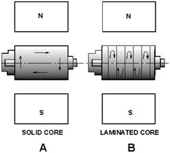
Figure 1-11. - Eddy currents in dc generator armature cores.
As you can see, eddy current losses are kept low when the core material is made up of many thin sheets
of metal. Laminations in a small generator armature may be as thin as 1/64 inch. The laminations are insulated
from each other by a thin coat of lacquer or, in some instances, simply by the oxidation of the surfaces.
Oxidation is caused by contact with the air while the laminations are being annealed. The insulation value need
not be high because the voltages induced are very small. Most generators use armatures with laminated
cores to reduce eddy current losses. Q15. How can eddy current be reduced? Hysteresis
Losses
Hysteresis loss is a heat loss caused by the magnetic properties of the armature. When an armature core is in a
magnetic field, the magnetic particles of the core tend to line up with the magnetic field. When the armature core
is rotating, its magnetic field keeps changing direction. The continuous movement of the magnetic particles, as
they try to align themselves with the magnetic field, produces molecular friction. This, in turn, produces heat.
This heat is transmitted to the armature windings. The heat causes armature resistances to increase. To
compensate for hysteresis losses, heat-treated silicon steel laminations are used in most dc generator armatures.
After the steel has been formed to the proper shape, the laminations are heated and allowed to cool. This
annealing process reduces the hysteresis loss to a low value.
The PRACTICAL DC GENERATOR The actual construction and operation of a practical dc generator differs somewhat from our
elementary generators. The differences are in the construction of the armature, the manner in which the armature
is wound, and the method of developing the main field. A generator that has only one or two armature loops
has high ripple voltage. This results in too little current to be of any practical use. To increase the amount of
current output, a number of loops of wire are used. These additional loops do away with most of the ripple. The
loops of wire, called windings, are evenly spaced around the armature so that the distance between each winding is
the same.
The commutator in a practical generator is also different. It has several segments instead of two or four, as in
our elementary generators. The number of segments must equal the number of armature coils.
GRAMME-RING ARMATURE The diagram of a GRAMME-RING armature is shown in figure 1-12, view A. Each
coil is connected to two commutator segments as shown. One end of coil 1goes to segment A, and the other end of
coil 1 goes to segment B. One end of coil 2 goes to segment C, and the other end of coil 2 goes to segment B. The
rest of the coils are connected in a like manner, in series, around the armature. To complete the series
arrangement, coil 8 connects to segment A. Therefore, each coil is in series with every other coil.
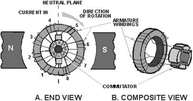
Figure 1-12. - Gramme-ring armature. Figure 1-12, view B shows a composite view of a Gramme-ring armature. It illustrates more
graphically the physical relationship of the coils and commutator locations. The windings of a Gramme-ring
armature are placed on an iron ring. a disadvantage of this arrangement is that the windings located on the inner
side of the iron ring cut few lines of flux. Therefore, they have little, if any, voltage induced in them. For
this reason, the Gramme-ring armature is not widely used. DRUM-TYPE ARMATURE A
drum-type armature is shown in figure 1-13. The armature windings are placed in slots cut in a drum-shaped iron
core. Each winding completely surrounds the core so that the entire length of the conductor cuts the main magnetic
field. Therefore, the total voltage induced in the armature is greater than in the Gramme-ring. You can see that
the drum-type armature is much more efficient than the Gramme-ring. This accounts for the almost universal use of
the drum-type armature in modem dc generators.
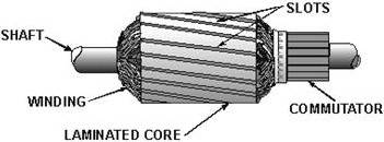
Figure 1-13. - Drum-type armature.
Drum-type armatures are wound with either of two types of windings - the LAP WINDING or the WAVE WINDING.
The lap winding is illustrated in figure 1-14, view a This type of winding is used in dc generators designed for
high-current applications. The windings are connected to provide several parallel paths for current in the
armature. For this reason, lap-wound armatures used in dc generators require several pairs of poles and brushes.

Figure 1-14. - Types of windings used on drum-type armatures. Figure 1-14, view B, shows a wave winding on a drum-type armature. This type of winding is used in dc
generators employed in high-voltage applications. Notice that the two ends of each coil are connected to
commutator segments separated by the distance between poles. This configuration allows the series addition of the
voltages in all the windings between brushes. This type of winding only requires one pair of brushes. In practice,
a practical generator may have several pairs to improve commutation. Q16. Why are drum-type armatures
preferred over the Gramme-ring armature in modern dc generators? Q17. Lap windings are used in
generators designed for what type of application? FIELD EXCITATION When a dc
voltage is applied to the field windings of a dc generator, current flows through the windings and sets up a
steady magnetic field. This is called FIELD EXCITATION. This excitation voltage can be produced by the
generator itself or it can be supplied by an outside source, such as a battery. a generator that supplies its own
field excitation is called a SELF-EXCITED GENERATOR. Self-excitation is possible only if the field pole pieces
have retained a slight amount of permanent magnetism, called RESIDUAL MAGNETIsM. When the generator starts
rotating, the weak residual magnetism causes a small voltage to be generated in the armature. This small voltage
applied to
the field coils causes a small field current. Although small, this field current strengthens the
magnetic field and allows the armature to generate a higher voltage. The higher voltage increases the field
strength, and so on. This process continues until the output voltage reaches the rated output of the generator.
Classification of GENERATORS Self-excited generators are classed according to the type of
field connection they use. There are three general types of field connections - Series-WOUND, Shunt-WOUND
(parallel), and COMPOUND-WOUND. Compound-wound generators are further classified as cumulative-compound and
differential-compound. These last two classifications are not discussed in this chapter.
Series-Wound Generator
In the series-wound generator, shown in figure 1-15, the field windings are connected in series with the armature.
Current that flows in the armature flows through the external circuit and through the field windings. The external
circuit connected to the generator is called the load circuit.
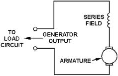
Figure 1-15. - Series-wound generator. A series-wound generator uses very low resistance field coils, which consist of a few turns of large
diameter wire. The voltage output increases as the load circuit starts drawing more current. Under
low-load current conditions, the current that flows in the load and through the generator is small. Since small
current means that a small magnetic field is set up by the field poles, only a small voltage is induced in the
armature. If the resistance of the load decreases, the load current increases. Under this condition, more current
flows through the field. This increases the magnetic field and increases the output voltage. a series-wound dc
generator has the characteristic that the output voltage varies with load current. This is undesirable in most
applications. For this reason, this type of generator is rarely used in everyday practice. The
series-wound generator has provided an easy method to introduce you to the subject of self- excited generators.
Shunt-Wound Generators In a shunt-wound generator, like the one shown in
figure 1-16, the field coils consist of many turns of small wire. They are connected in parallel with the load. In
other words, they are connected across the output voltage of the armature.
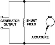
Figure 1-16. - Shunt-wound generator. Current in the field windings of a shunt-wound generator is independent of the load current (currents in
parallel branches are independent of each other). Since field current, and therefore field strength, is not
affected by load current, the output voltage remains more nearly constant than does the output voltage of the
series-wound generator. In actual use, the output voltage in a dc shunt-wound generator varies inversely
as load current varies. The output voltage decreases as load current increases because the voltage drop across the
armature resistance increases (E = IR). In a series-wound generator, output voltage varies directly with
load current. In the shunt-wound generator, output voltage varies inversely with load current. a combination of
the two types can overcome the disadvantages of both. This combination of windings is called the compound-wound dc
generator.
Compound-Wound Generators Compound-wound generators have a series-field winding in
addition to a shunt-field winding, as shown in figure 1-17. The shunt and series windings are wound on the same
pole pieces.
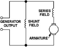
Figure 1-17. - Compound-wound generator. In the compound-wound generator when load current increases, the armature voltage decreases just as in
the shunt-wound generator. This causes the voltage applied to the shunt-field winding to decrease, which results
in a decrease in the magnetic field. This same increase in load current, since it flows through the series
winding, causes an increase in the magnetic field produced by that winding. By proportioning the two
fields so that the decrease in the shunt field is just compensated by the increase in the series field, the output
voltage remains constant. This is shown in figure 1-18, which shows the voltage characteristics of the series-,
shunt-, and compound-wound generators. As you can see, by proportioning the effects of the two fields (series and
shunt), a compound-wound generator provides a constant output voltage under varying load conditions. Actual curves
are seldom, if ever, as perfect as shown.
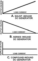
Figure 1-18. - Voltage output characteristics of the series-, shunt-, and compound-wound dc
generators.
Q18. What are the three classifications of dc generators? Q19. What is the main
disadvantage of series generators? GENERATOR CONSTRUCTION
Figure 1-19, views a through E, shows the component parts of dc generators. Figure 1-20 shows the entire generator
with the component parts installed. The cutaway drawing helps you to see the physical relationship of the
components to each other.
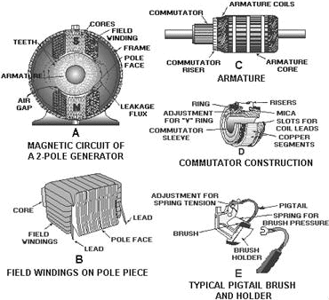
Figure 1-19. - Components of a dc generator.
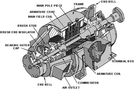
Figure 1-20. - Construction of a dc generator (cutaway drawing). Voltage REGULATION The regulation of a generator refers to the Voltage CHANGE
that takes place when the load changes. It is usually expressed as the change in voltage from a no-load condition
to a full-load condition, and is expressed as a percentage of full-load. It is expressed in the following formula:

where EnL is the no-load terminal voltage and EfL is the full-load terminal
voltage of the generator. For example, to calculate the percent of regulation of a generator with a no-load
voltage of 462 volts and a full-load voltage of 440 volts Given:
· No-load voltage 462 V · Full-load voltage 440 V Solution:
| - |
Matter, Energy,
and Direct Current |
| - |
Alternating Current and Transformers |
| - |
Circuit Protection, Control, and Measurement |
| - |
Electrical Conductors, Wiring Techniques,
and Schematic Reading |
| - |
Generators and Motors |
| - |
Electronic Emission, Tubes, and Power Supplies |
| - |
Solid-State Devices and Power Supplies |
| - |
Amplifiers |
| - |
Wave-Generation and Wave-Shaping Circuits |
| - |
Wave Propagation, Transmission Lines, and
Antennas |
| - |
Microwave Principles |
| - |
Modulation Principles |
| - |
Introduction to Number Systems and Logic Circuits |
| - |
- Introduction to Microelectronics |
| - |
Principles of Synchros, Servos, and Gyros |
| - |
Introduction to Test Equipment |
| - |
Radio-Frequency Communications Principles |
| - |
Radar Principles |
| - |
The Technician's Handbook, Master Glossary |
| - |
Test Methods and Practices |
| - |
Introduction to Digital Computers |
| - |
Magnetic Recording |
| - |
Introduction to Fiber Optics |
| Note: Navy Electricity and Electronics Training
Series (NEETS) content is U.S. Navy property in the public domain. |
|


