NEETS Module 5 - Introduction to Generators and Motors
Pages i,
1-1,
1-11,
1-21,
1-31,
2-1,
2-11,
3-1,
3-11,
4-1,
4-11, Index
Chapter 1
Direct CURRENT GENERATORS
Learning Objectives
Upon completion of the chapter you will be able to: 1.
State the principle by which generators convert mechanical energy to electrical
energy. 2. State the rule to be applied when you determine the
direction of induced EMF in a coil. 3. State the purpose of slip
rings. 4. State the reason why no EMF is induced in a rotating
coil as it passes through a neutral plane. 5. State what component
causes a generator to produce direct current rather than alternating current.
6. Identify the point at which the brush contact should change from one commutator
segment to the next. 7. State how field strength can be varied
in a dc generator. 8. Describe the cause of sparking between
brushes and commutator. 9. State what is meant by "armature reaction."
10. State the purpose of interpoles. 11. Explain the effect
of motor reaction in a dc generator. 12. Explain the causes of
armature losses. 13. List the types of armatures used in dc generators.
14. State the three classifications of dc generators. 15.
State the term that applies to voltage variation from no-load to full-load conditions
and how it is expressed as a percentage. 16. State the term that
describes the use of two or more generators to supply a common load.
17. State the purpose of a dc generator that has been modified to function
as an amplidyne.
Introduction
A generator is a machine that converts mechanical energy into electrical
energy by using the principle of magnetic induction. This principle is explained
as follows: Whenever a conductor is moved within a magnetic field in
such a way that the conductor cuts across magnetic lines of flux, voltage is generated
in the conductor.
The AMOUNT of voltage generated depends on (1) the strength of the magnetic field,
(2) the angle at which the conductor cuts the magnetic field, (3) the speed at which
the conductor is moved, and (4) the length of the conductor within the magnetic
field. The POLARITY of the voltage depends on the direction of the
magnetic lines of flux and the direction of movement of the conductor. To determine
the direction of current in a given situation, the LEFT-Hand RULE for GENERATORS
is used. This rule is explained in the following manner. Extend the
thumb, forefinger, and middle finger of your left hand at right angles to one another,
as shown in figure 1-1. Point your thumb in the direction the conductor is being
moved. Point your forefinger in the direction of magnetic flux (from north to south).
Your middle finger will then point in the direction of current flow in an external
circuit to which the voltage is applied.
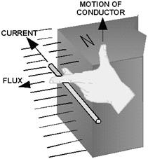
Figure 1-1. - Left-hand rule for generators.
The ELEMENTARY GENERATOR
The simplest elementary generator that can be built is an ac generator.
Basic generating principles are most easily explained through the use of the
elementary ac generator. For this reason, the ac generator will be discussed first.
The dc generator will be discussed later. An elementary generator (fig.
1-2) consists of a wire loop placed so that it can be rotated in a stationary magnetic
field. This will produce an induced EMF in the loop. Sliding contacts (brushes)
connect the loop to an external circuit load in order to pick up or use the induced
EMF.

Figure 1-2. - The elementary generator.
The pole pieces (marked N and S) provide the magnetic field. The pole
pieces are shaped and positioned as shown to concentrate the magnetic field as close
as possible to the wire loop. The loop of wire that rotates through the field is
called the ARMATURE. The ends of the armature loop are connected to rings called
SLIP RINGS. They rotate with the armature. The brushes, usually made of carbon,
with wires attached to them, ride against the rings. The generated voltage appears
across these brushes. The elementary generator produces a voltage in
the following manner (fig. 1-3). The armature loop is rotated in a clockwise direction.
The initial or starting point is shown at position A. (This will be considered the
zero-degree position.) At 0º the armature loop is perpendicular to the magnetic
field. The black and white conductors of the loop are moving parallel to the field.
The instant the conductors are moving parallel to the magnetic field, they do not
cut any lines of flux. Therefore, no EMF is induced in the conductors, and the meter
at position a indicates zero. This position is called the NEUTRAL Plane. As the
armature loop rotates from position a (0º) to position B (90º), the conductors cut
through more and more lines of flux, at a continually increasing angle. At 90º
they are cutting through a maximum number of lines of flux and at maximum angle.
The result is that between 0º and 90º , the induced EMF in the conductors
builds up from zero to a maximum value. Observe that from 0º to 90º , the
black conductor cuts DOWN through the field. At the same time the white conductor
cuts UP through the field. The induced EMFs in the conductors are series-adding.
This means the resultant voltage across the brushes (the terminal voltage) is the
sum of the two induced voltages. The meter at position B reads maximum value. As
the armature loop continues rotating from 90º (position B) to 180º (position
C), the conductors which were cutting through a maximum number of lines of flux
at position B now cut through fewer lines. They are again moving parallel to the
magnetic field at position C. They no longer cut through any lines of flux. As the
armature rotates from 90º to 180º , the induced voltage will decrease to zero
in the same manner that it increased during the rotation from 0º to 90º .
The meter again reads zero. From 0º to 180º the conductors of the armature
loop have been moving in the same direction through the magnetic field. Therefore,
the polarity of the induced voltage has remained the same. This is shown by points
A through C on the graph. As the loop rotates beyond 180º (position C), through
270º (position D), and back to the initial or starting point (position A),
the direction of the cutting action of the conductors through the magnetic field
reverses. Now the black conductor cuts UP through the field while the white conductor
cuts DOWN through the field. As a result, the polarity of the induced voltage reverses.
Following the sequence shown by graph points C, D, and back to A, the voltage will
be in the direction opposite to that
shown from points A, B, and C. The terminal voltage will be the same as it was
from a to C except that the polarity is reversed (as shown by the meter deflection
at position D). The voltage output waveform for the complete revolution of the loop
is shown on the graph in figure 1-3.
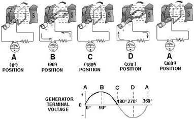
Figure 1-3. - Output voltage of an elementary generator during one revolution.
Q1. Generators convert mechanical motion to electrical
energy using what principle? Q2. What rule should you use to determine the direction of induced EMF in a coil? Q3.
What is the purpose of the slip rings? Q4. Why is no
EMF induced in a rotating coil when it passes through the neutral plane?
The ELEMENTARY DC GENERATOR
A single-loop generator with each terminal connected to a segment
of a two-segment metal ring is shown in figure 1-4. The two segments of the split
metal ring are insulated from each other. This forms a simple COMMUTATOR. The commutator
in a dc generator replaces the slip rings of the ac generator. This is the main
difference in their construction. The commutator mechanically reverses the armature
loop connections to the external circuit. This occurs at the same instant that the
polarity of the voltage in the armature loop reverses. Through this process the
commutator changes the generated ac voltage to a pulsating dc voltage as shown in
the graph of figure 1-4. This action is known as commutation. Commutation is described
in detail later in this chapter.

Figure 1-4. - Effects of commutation.
For the remainder of this discussion, refer to figure 1-4, parts a
through D. This will help you in following the step-by-step description of the operation
of a dc generator. When the armature loop rotates clockwise from position a to position
B, a voltage is induced in the armature loop which causes a current in a direction
that deflects the meter to the right. Current flows through loop, out of the negative
brush, through the meter and the load, and back through the positive brush to the
loop. Voltage reaches its maximum value at point B on the graph for reasons explained
earlier. The generated voltage and the current fall to zero at position C. At this
instant each brush makes contact with both segments of the commutator. As the armature
loop rotates to position D, a voltage is again induced in the loop. In this case,
however, the voltage is of opposite polarity. The voltages induced
in the two sides of the coil at position D are in the reverse direction to that
of the voltages shown at position B. Note that the current is flowing from the black
side to the white side in position B and from the white side to the black side in
position D. However, because the segments of the commutator have rotated with the
loop and are contacted by opposite brushes, the direction of current flow through
the brushes and the meter remains the same as at position B. The voltage developed
across the brushes is pulsating and unidirectional (in one direction only). It varies
twice during each revolution between zero and maximum. This variation is called
RIPPLE. A pulsating voltage, such as that produced in the preceding
description, is unsuitable for most applications. Therefore, in practical generators
more armature loops (coils) and more commutator segments are used to produce an
output voltage waveform with less ripple. Q5. What component
causes a generator to produce dc voltage rather than ac voltage at its output terminals?
Q6. At what point should brush contact change from one commutator segment
to the next? Q7. An elementary, single coil, dc generator
will have an output voltage with how many pulsations per revolution?
EFFECTS of ADDING ADDITIONAL Coils and POLES The
effects of additional coils may be illustrated by the addition of a second coil
to the armature. The commutator must now be divided into four parts since there
are four coil ends (see fig. 1-5). The coil is rotated in a clockwise direction
from the position shown. The voltage induced in the white coil, DECREASES for The
NEXT 90º of rotation (from maximum to zero). The voltage induced in the black
coil INCREASES from zero to maximum at the same time. Since there are four segments
in the commutator, a new segment passes each brush every 90º instead of every
180º . This allows the brush to switch from the white coil to the black coil at
the instant the voltages in the two coils are equal. The brush remains in contact
with the black coil as its induced voltage increases to maximum, level B in the
graph. It then decreases to level A, 90º later. At this point, the brush will
contact the white coil again.
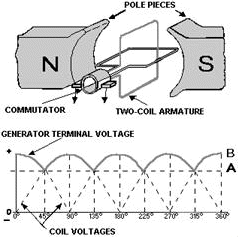
Figure 1-5. - Effects of additional coils.
The graph in figure 1-5 shows the ripple effect of the voltage when
two armature coils are used. Since there are now four commutator segments in the
commutator and only two brushes, the voltage cannot fall any lower than at point
A. Therefore, the ripple is limited to the rise and fall between points a and B
on the graph. By adding more armature coils, the ripple effect can be further reduced.
Decreasing ripple in this way increases the effective voltage of the output.
Note: Effective voltage is the equivalent level of dc voltage, which will cause
the same average current through a given resistance. By using additional armature
coils, the voltage across the brushes is not allowed to fall to as low a level between
peaks. Compare the graphs in figure 1-4 and 1-5. Notice that the ripple has been
reduced. Practical generators use many armature coils. They also use more than one
pair of magnetic poles. The additional magnetic poles have the same effect on ripple
as did the additional armature coils. In addition, the increased number of poles
provides a stronger magnetic field (greater number of flux lines). This, in turn,
allows an increase in output voltage because the coils cut more lines of flux per
revolution. Q8. How many commutator segments are required
in a two-coil generator?
ELECTROMagnetic POLES Nearly all practical generators use electromagnetic poles instead of the permanent magnets used in our elementary
generator. The electromagnetic field poles consist of coils of insulated copper
wire wound on soft iron cores, as shown in figure 1-6. The main advantages of using
electromagnetic poles are (1) increased field strength and (2) a means of controlling
the strength of the fields. By varying the input voltage, the field strength is
varied. By varying the field strength, the output voltage of the generator can be
controlled.
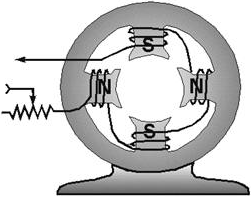
Figure 1-6. - Four-pole generator (without armature).
Q9. How can field strength be varied in a practical dc
generator? COMMUTATION Commutation is
the process by which a dc voltage output is taken from an armature that has an ac
voltage induced in it. You should remember from our discussion of the elementary
dc generator that the commutator mechanically reverses the armature loop connections
to the external circuit. This occurs at the same instant that the voltage polarity
in the armature loop reverses. a dc voltage is applied to the load because the output
connections are reversed as each commutator segment passes under a brush. The segments
are insulated from each other. In figure 1-7, commutation occurs simultaneously
in the two coils that are briefly short-circuited by the brushes. Coil B is short-circuited
by the negative brush. Coil Y, the opposite coil, is short-circuited by the positive
brush. The brushes are positioned on the commutator so that each coil is short-circuited
as it moves through its own electrical neutral plane. As you have seen previously,
there is no voltage generated in the coil at that time. Therefore, no sparking can
occur between the commutator and the brush. Sparking between the brushes and the
commutator is an indication of improper commutation. Improper brush placement is
the main cause of improper commutation.

Figure 1-7. - Commutation of a dc generator.
Q10. What causes sparking between the brushes and the
commutator? ARMATURE REACTION From previous
study, you know that all current-carrying conductors produce magnetic fields. The
magnetic field produced by current in the armature of a dc generator affects the
flux pattern and distorts the main field. This distortion causes a shift in the
neutral plane, which affects commutation. This change in the neutral plane and the
reaction of the magnetic field is called ARMATURE REACTION. You know
that for proper commutation, the coil short-circuited by the brushes must be in
the neutral plane. Consider the operation of a simple two-pole dc generator, shown
in figure 1-8. View a of the figure shows the field poles and the main magnetic
field. The armature is shown in a simplified view in views B and C with the cross
section of its coil represented as little circles. The symbols within the circles
represent arrows. The dot represents the point of the arrow coming toward you, and
the cross represents the tail, or feathered end, going away from you. When the armature
rotates clockwise, the sides of the coil to the left will have current flowing toward
you, as indicated by the dot. The side of the coil to the right will have current
flowing away from you, as indicated by the cross. The field generated around each
side of the coil is shown in view B of figure 1-8. This field increases in strength
for each wire in the armature coil, and sets up a magnetic field almost perpendicular
to the main field.
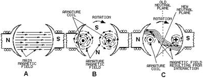
Figure 1-8. - Armature reaction.
Now you have two fields - the main field, view A, and the field around
the armature coil, view B. View C of figure 1-8 shows how the armature field distorts
the main field and how the neutral plane is shifted in the direction of rotation.
If the brushes remain in the old neutral plane, they will be short- circuiting coils
that have voltage induced in them. Consequently, there will be arcing between the
brushes and commutator. To prevent arcing, the brushes must be shifted
to the new neutral plane. Q11. What is armature reaction?
COMPENSATING WINDINGS and INTERPOLES Shifting the
brushes to the advanced position (the new neutral plane) does not completely solve
the problems of armature reaction. The effect of armature reaction varies with the
load current. Therefore, each time the load current varies, the neutral plane shifts.
This means the brush position must be changed each time the load current varies.
In small generators, the effects of armature reaction are reduced by actually mechanically
shifting the position of the brushes. The practice of shifting the brush position
for each current variation is not practiced except in small generators. In larger
generators, other means are taken to eliminate armature reaction. COMPENSATING WINDINGS
or INTERPOLES are used for this purpose (fig. 1-9). The compensating windings consist
of a series of coils embedded in slots in the pole faces. These coils are connected
in series with the armature. The series-connected compensating windings produce
a magnetic field, which varies directly with armature current. Because the compensating
windings are wound to produce a field that opposes the magnetic field of the armature,
they tend to cancel the effects of the armature magnetic field. The neutral plane
will remain stationary and in its original position for all values of armature current.
Because of this, once the brushes have been set correctly, they do not have to be
moved again.

Figure 1-9. - Compensating windings and interpoles.
Another way to reduce the effects of armature reaction is to place
small auxiliary poles called "interpoles" between the main field poles. The interpoles
have a few turns of large wire and are connected in series with the armature. Interpoles
are wound and placed so that each interpole has the same magnetic polarity as the
main pole ahead of it, in the direction of rotation. The field generated by the
interpoles produces the same effect as the compensating winding. This field, in
effect, cancels the armature reaction for all values of load current by causing
a shift in the neutral plane opposite to the shift caused by armature reaction.
The amount of shift caused by the interpoles will equal the shift caused by armature
reaction since both shifts are a result of armature current. Q12.
What is the purpose of interpoles? MOTOR REACTION IN a GENERATOR
When a generator delivers current to a load, the armature current creates a magnetic
force that opposes the rotation of the armature. This is called MOTOR REACTION.
A single armature conductor is represented in figure 1-10, view A. When the conductor
is stationary, no voltage is generated and no current flows. Therefore, no force
acts on the conductor. When the conductor is moved downward (fig. 1- 10, view B)
and the circuit is completed through an external load, current flows through the
conductor in the direction indicated. This sets up lines of flux around the conductor
in a clockwise direction.
| - |
Matter, Energy,
and Direct Current |
| - |
Alternating Current and Transformers |
| - |
Circuit Protection, Control, and Measurement |
| - |
Electrical Conductors, Wiring Techniques,
and Schematic Reading |
| - |
Generators and Motors |
| - |
Electronic Emission, Tubes, and Power Supplies |
| - |
Solid-State Devices and Power Supplies |
| - |
Amplifiers |
| - |
Wave-Generation and Wave-Shaping Circuits |
| - |
Wave Propagation, Transmission Lines, and
Antennas |
| - |
Microwave Principles |
| - |
Modulation Principles |
| - |
Introduction to Number Systems and Logic Circuits |
| - |
- Introduction to Microelectronics |
| - |
Principles of Synchros, Servos, and Gyros |
| - |
Introduction to Test Equipment |
| - |
Radio-Frequency Communications Principles |
| - |
Radar Principles |
| - |
The Technician's Handbook, Master Glossary |
| - |
Test Methods and Practices |
| - |
Introduction to Digital Computers |
| - |
Magnetic Recording |
| - |
Introduction to Fiber Optics |
| Note: Navy Electricity and Electronics Training
Series (NEETS) content is U.S. Navy property in the public domain. |
|


