|
The concept of a decibel (dB) is understandably difficult and confusing for someone
just being introduced to it. Combining specifications for gain, power, and voltage
(and current, but not so often) that mix dB, dBm, dBW, watts, milliwatts, voltage,
millivolts, etc., often requires converting back and forth between linear values
and decibel values. This brief tutorial will help to clarify the difference between
working with decibels and working with linear values. Here is a
table of decibel power and volts with conversion to
watts and volts.
Anxiety Alert: Using decibels involves working with logarithms.
Logarithms (logs) were first conceived of in the early 1600s by Scottish mathematician
John Napier,
as a tool for simplifying multiplication and division operations by converting them
to faster and less error prone addition and subtraction operations, respectively.
This is made possible because of the way multiplication of two numbers expressed
as similar base numbers with exponents can be accomplished by merely adding the
exponents together. Division of those same numbers is accomplished by subtracting
the exponents. It is one of the laws of exponents, and looks like this:

Using actual numbers as an example, where x = 10, a = 4, b = 1:

The law of exponents works for any base number, not just 10. To wit:

People tend to make fewer mistakes when adding and subtracting numbers, so the
advantage of logarithms is apparent. Remember that logarithms were developed before
automatic mechanical or electronic computers were available. A
slide rule exploits the properties of
logarithms for calculation, but that is a separate major topic.
Those are simple examples, but hold for any base or exponent. In the absence
of a calculator, in order to be useful for general application you need a table
of numbers and their equivalent logarithms. Early log tables filled volumes, depending
on the spacing between numbers (1.000, 1.001, 1.002, 1.003, vs. 1.0, 1.1, 1.2, 1.3,
etc.). The good news for creators of
logarithm tables is that only a single 'decade' of numbers (e.g.,
1 through 10) is required since every preceding or seceding decade is a simple multiple
of a power of 10.
Note: I use base 10 in this discussion since that is the base of our common number
system - hence the term 'common logarithm' for base 10 logs. You might have heard
of natural
logarithms, which uses the base of
e, but e is not used very often when calculating scalar electrical power, voltage,
and current quantities (although it is used when phase angles are included, i.e.,
Euler's identity).
Natural logarithms are written as ln (x) without the 'e' subscript, whereas usually
base 10 logarithms are written simply as log (x) without the 10 subscript; i.e.,
not loge (x) or log10 (x), respectively.
Per a base=10 log table:
log (100,000) = 5, log
(10,000) = 4, log (1,000) = 3, log
(10) = 1
 The exception and special case is logx (0)
= Undefined. That is so because there is no power to which you can raise any number
and obtain 0 (zero). You can asymptotically approach zero, but you cannot get to
zero. There will never be the number zero displayed on a log scale; they usually
run from some power of 10 to some other power of ten. An example of log graph paper
is shown on the right. It has 5 'cycles' or 'decades' of range. Note there is no
zero on the y-axis. The exception and special case is logx (0)
= Undefined. That is so because there is no power to which you can raise any number
and obtain 0 (zero). You can asymptotically approach zero, but you cannot get to
zero. There will never be the number zero displayed on a log scale; they usually
run from some power of 10 to some other power of ten. An example of log graph paper
is shown on the right. It has 5 'cycles' or 'decades' of range. Note there is no
zero on the y-axis.
The base-10 (common) logarithm of a number, then, is the exponent that 10 must
be raised to in order to obtain that number. In other words, since 10 raised to
the power of 2 is equal to 100 (102 = 100), the base-10 log of 100 is
2 (log10 100 = 2).
This is the basic law of logarithms:
logc (a)
= b, therefore cb
= a
Performing the same multiplications and divisions as done at the top of the page
by using actual logarithms:
10,000 * 10 = 100,000 and
10,000 ÷ 10 = 1,000
4 + 1 = 5 and 4
- 1 = 3
That's fine, but what you end up with is the logarithm of the number you seek.
Question: Except for a simple example like this, how do you get the answer you need?
Answer: Look up the antilogarithm (antilog) of the result. In this case:
antilog 5 = 100,000 and
antilog 3 = 1,000
A tougher, and more likely example with numbers that are not integer powers of
10, might look something like the following:
x = 1.28 * 3.70 * 0.559 * 26.4
log (x) = log (1.28) + log (3.70) + log (0.559) + log
(26.4)
log (x) = 0.1072 + 0.5682 + (-0.2526) + 1.4216 = 1.8444
 Since
the logarithm of 'x' equals 1.8444, the antilog equals 'x,' which is
69.9 Since
the logarithm of 'x' equals 1.8444, the antilog equals 'x,' which is
69.9
Check: x = 1.28 * 3.70 * 0.559 * 26.4 =
69.9
I used my calculator to look up the logs and antilogs for those numbers, but
prior to 1972 when Hewlett Packard (HP) introduced their
HP-35 scientific
calculator, the average person without access to a corporate or university mainframe
computer needed to use a log table to perform such calculations.
Who bothers to use logarithms today, you might ask? Lots of people, including
me, quite often when calculating cascaded
system parameters like noise figure (NF) and intercept points (IP). Simple addition
and subtraction of gain dB and power dBm values don't work with NF and IP. The governing
formulas use multiplication and division of linear gain and power values, which
requires first converting dB and/or dBm to linear numbers (gain ratio and mW) using
antilogs, performing the cascade calculations, and then converting the result back
to dB and/or dBm using logs.
Not all system cascade operations require converting back and forth. For instance
if only the total system gain and/or output power level is needed, then calculations
can be carried out with either linear units (mW and multipliers) or logarithmic
units (dBm and dB, respectively).
The Definition of 'dB' and 'dBm'
A decibel (dB) in electrical engineering is defined as 10 times the base-10 logarithm
of a ratio between two power levels; e.g., Pout/Pin (gain,
in other words). To wit:
N dB = 10 * log10 (P1/P2)
All gains greater than 1 are therefore expressed as positive decibels (>0),
and gains of less than 1 are expressed as negative decibels (<0). Note that for
cases most of us encounter, the linear ratio of P1/P2 must be a positive number
(>0) since the logarithm of 0 is undefined and the logarithm of negatives numbers
are complex (they contain both a real and an imaginary part). The dB value, though,
can theoretically take on any value between -∞ and +∞, including 0,
which is a gain of 1 [10 * log (1) = 0 dB].
'dBm' is a decibel-based unit of power that is referenced to 1 mW. Since
0 dB of gain is equal to a gain of 1, 1 mW of power is 0 dB greater
than 1 mW, or 0 dBm. Similarly, a power unit of dBW is decibels relative
to 1 W of power.
1 mW = 0 dBm
Accordingly, all dBm values greater than 0 are larger than 1 mW, and all
dBm values less than 0 are smaller than 1 mW (see Fig. 1). For instance, +3.01 dBm
is 3.01 dB greater than 1 mW; i.e., or 0 dBm + 3.01 dB = +3.01 dBm
(2 mW). -3.01 dBm is 3.01 dB less than 1 mW; i.e., or
0 dBm + (-3.01) dB = -3.01 dBm (0.5 mW).
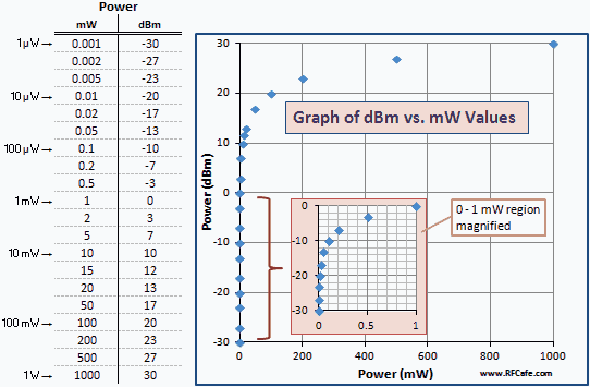
The following table gives some numerical examples so you can see the correlation
between mW and dBm. The same set of values plotted on a logarithmic scale would
produce a straight line. Because of the logarithmic relationship, the graph bunches
the smaller values against the left vertical axis. A magnified version of the 0 to 1 mW
region is inset for clarity.

Fig. 1 - Graph of Power in Units of dBm vs. mW
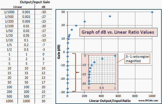
Fig. 2 is a table and graph of dB vs. linear gain ratios similar to the dBm vs.
mW in Fig. 1. Note that the numbers and curves are exactly the same; only the axis
labels are changed. That is because dBm is a unit of power expressed in dB relative
to 1 mW (0 dBm).

Fig. 2 - Graph of Gain in Units of dBm vs. Linear Ratio
Linear Gain (output/input ratio) vs. Logarithmic (decibels, dB) Gain
Fundamentally, gain is a multiplication (or division) factor. As an example,
an amplifier might have a gain that increases the signal by a factor of 4 (i.e.,
4x) from input to output (see Fig. 3). If a 1 mW (0 dBm) signal is fed
into the amplifier, then 1 mW * 4 = 4 mW comes out.
In terms of decibels, a factor of 4 is equivalent to 10 * log (4) = 6.02 dB,
so 0 dBm in plus 6.02 dB of gain yields +6.02 dBm at the output.
1 mW *
4 = 4 mW
0 dBm +
6.02 dB = 6.02 dBm

Fig. 3 - Single amplifier gain.
Combining Gains (linear and dB) w/Positive Values
If an amplifier with a gain of 4 is in series with a second amplifier with a
gain of 6, then the total gain is 4 * 6 = 24. In terms of decibels,
a factor of 6 is equivalent to 10 * log (6) = 7.78 dB,
and a factor of 24 is equivalent to 10 * log (24) = 13.8 dB.
Just as 4 x 6 = 24 (linear gain), 6.02 dB + 7.78 dB = 13.8 dB
(decibel gain).
If a 1 mW signal (0 dBm) is fed into the amplifier, then 4 mW comes
out of the first amplifier, and 24 mW comes out of the second amplifier. See
Fig. 4.
1 mW *
4 * 6 =
24 mW
0 dBm +
6.02 dB + 7.78 dB
= 13.8 dBm

Fig. 4 - Cascaded dual amplifier gain.
Combining Gain and Loss (linear and dB)
This next example shows what happens when a gain < 1 (a loss) is encountered,
where an attenuator with a gain of 1/6 is placed after the first amplifier instead
of having a second amplifier. See Fig. 5.
4 * 1/6 = 2/3 (linear gain). Similarly 6.02 dB - 7.78 dB = -1.76 dB
(decibel gain).
As with the previous example, if a 1 mW signal (0 dBm) is fed into the amplifier
with a gain of 4, then 4 mW comes out. That 4 mW then goes into the attenuator
with a linear gain of 1/6 and comes out at a power level of 4/6 mW (2/3 mW).
The total gain in this case is 4/6 = 2/3, so the output power will
actually be less than the input power.
1 mW *
4 * 1/6 =
2/3 mW = 0.67 mW
0 dBm +
6.02 dB + (-7.78 dB)
= -1.76 dBm

Fig. 5 - Cascaded amplifier gain and attenuator.
Note that power levels greater than 0 dBm sometimes include the 'plus' sign
(+) in order to emphasize that it is not negative. This is particularly so when
power levels are displayed on a block diagram where both positive and negative values
are present.
Summary
When making power measurements in the laboratory or in the field, most people
find it easier to add and subtract gains and power levels than to multiply and divide
gains and power levels. dB and dBm units make that possible. The important thing
to remember is to never mix
linear gain (ratio) units and wattage power (mW) units with logarithmic gain (dB)
and power (dBm) units.
Quantities must be either in all linear or all decibel units. The following type
of calculation is NOT
allowed because it mixes linear values with logarithmic values.
12 mW + 34 mW + 8 mW + 20 dB
Supplemental Information on Logarithms
Logarithms of Products
A property of logarithms used implicitly above states the following, and is the
basis for being able to add and subtract logarithm values instead of multiplying
their linear equivalents.
log (h*j)= log (h) + log (j), and
log (h/j)= log (h) - log (j)
therefore,
log (h*j/k*m/n) = log (h) + log (j) - log (k) + log
(m) - log (n)
'h * j / k * m / n' might represent a cascade of components that have three devices
(h, j, and m) each with gain >1 and two devices (k and n) each with a gain <1
(see Fig. 6). The total system gain can be calculated either by multiplying all
the linear gain values together or adding all the decibel gain values together.

Fig. 6 - Cascaded components
See more on properties of logarithms and
properties of exponents.
Logarithms of Exponents
The following is important for understanding why power gain in terms
of power is 10 * log (Pout/Pin) dB,
while power gain in terms of voltage is 20 * log (Vout/Vin) dB.
log (cf)
= f * log (c),
which is so because cf is equal to c multiplied by
itself 'f' times. For example, if f = 4:
cf = c4
= c * c * c * c
log (c4) = log (c * c * c * c) = log
(c) + log (c) + log (c) + log (c) = 4 * log (c).
Power Gain Based on Power vs. Power Gain Based on Voltage
Power gain is Pout/Pin, and voltage gain is Vout/Vin.
Power gain based on a power ratio in decibels is defined as 10 * log (Pout/Pin).
Power gain in terms of voltage, is [(Vout2/R)/(Vin2/R)],
since per Ohm's law P = V2/R. The 'R' in the denominators cancel
leaving Vout2/Vin2 , which is equal
to (Vout/Vin)2, as defined by the rule of exponents
that says ac/bc = (a/b)c. Hence:
10 * log  = 10 * 2 * log = 10 * 2 * log
 = 20 * log = 20 * log

Important Note: Voltage gain in terms of voltage is 10 * log (Vout/Vin) dB,
the same as with power gain in terms of power. It is only when
power gain is expressed in terms of voltage that the 20 * log (Vout/Vin) dB
equation applies. This is a common point of confusion.
Gain <1 (Loss) as Negative Decibels
No operation in mathematics is arbitrary, and that goes for why a signal power
loss (gain <1) is portrayed as a negative value, and hence is subtracted during
a cascade calculation. It is a simple demonstration, but worthy of mentioning.
log (1/f) = log (1) - log (f) = 0 - log (f) = -log (f)
Please send any comments or corrections to
kmblatt83@aol.com.
Posted January 9, 2023
(updated from original
post on 10/18/2016)
|


 = 10 * 2 * log
 = 20 * log


