Module 12 − Modulation Principles
Pages i,
1−1,
1−11,
1−21,
1−31,
1−41,
1−51,
1−61,
1−71,
2−1,
2−11,
2−21,
2−31,
2−41,
2−51,
2−61,
3−1,
3−11,
3−21,
3−31, AI−1, Index, Assignment 1, 2

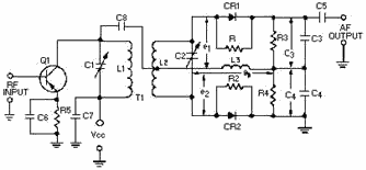
The Common-Base DETECTOR
is an amplifying detector that is used in portable receivers.
 The SLOPE DETECTOR is the simplest form of frequency detector. It is essentially a tank
circuit tuned slightly away from the desired fm carrier. The FOSTER-SEELEY DIsCRIMINATOR uses a double tuned RF transformer to convert frequency changes of the received fm signal into amplitude
variations of the RF wave.
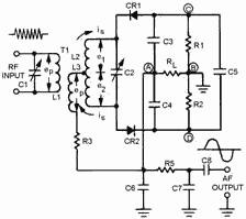
 The RATIO DETECTOR uses a double-tuned transformer connected so that the instantaneous
frequency variations of the fm input signal are converted into instantaneous amplitude variations. 3-31
The GATED-BEAM DETECTOR uses a specially-designed tube to limit, detect, and amplify the
received fm signal. 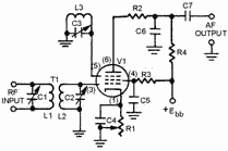
Phase DEMODULATION may be accomplished using a frequency discriminator or a quadrature
detector. 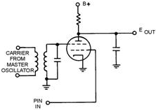
3-32
PEAK DETECTION uses the amplitude, or duration, of a pulse to charge a holding capacitor and
restore the modulating waveform.
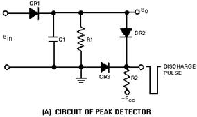 A Low-PASS FILTER is used to demodulate DM by averaging the pulse amplitude over the
entire period between pulses. PULSE CONVERSION is used to convert PPM, PDM, or PCM to PDM or
PAM for demodulation. Answers to Questions Q1. Through Q40. A-1. Re-creating original modulating
frequencies (intelligence) from radio frequencies. A-2. Circuit in which intelligence restoration is
achieved. A-3. a circuit that can detect the presence or absence of RF energy. A-4. An antenna,
tank circuit for tuning, rectifier for detection, filter to give constant output, and an indicator device. A-5. Heterodyning. A-6. By giving a different beat frequency for each signal. A-7. Regenerative
detector. A-8. Oscillator, mixer, and detector. A-9. (1) Sensitive to the type of modulation applied, (2)
nonlinear, and (3) provide filtering. A-10. The modulation envelope. A-11. Rectifies the RF pulses
in the received signal. 3-33
A-12. To filter the RF pulses and develop the modulating wave (intelligence) from the modulation
envelope.
A-13. The current-diode detector is in parallel with the input and load. A-14. When the input
voltage variations are too small to give a usable output from a series detector. A-15. Emitter-base
junction. A-16. R1. A-17. By the collector current flow through R4. A-18. Emitter-base junction. A-19. a diode detector followed by a stage of audio amplification. A-20. C1 and R1. A-21. Slope
detector.
A-22. Converting frequency variations of received fm signals to amplitude variations. A-23. a
double-tuned tank circuit. A-24. Rectify the RF voltage from the discriminator. A-25. Inductive. A-26. Suppresses amplitude noise without limiter stages. A-27. It helps to maintain a constant circuit
voltage to prevent noise fluctuations from interfering with the output. A-28. Limits, detects, and
amplifies. A-29. Both grids must be positively biased. A-30. Extreme simplicity, few components, and
ease of adjustment. A-31. In the amount and rate of phase shift of the carrier wave. A-32. Because
of the incidental frequency shift that is caused while phase-shifting a carrier wave that is similar to fm
modulation. A-33. The quadrature grid signal is excited by a reference from the transmitter. A-34.
Detecting the presence of RF energy. A-35. Pulse amplitude or pulse duration. A-36. At least 10 times the interpulse period. A-37.
By making the time constant for charging the capacitor at least 10 times the maximum received pulse width. 3-34
A-38. By averaging the value of the pulses over the period of the pulse-repetition rate.
A-39. PPM, PFM, and PCM are converted to either PDM or PAM for demodulation. A-40. It will discharge to
one-half its value between pulses. 3-35
| - |
Matter, Energy,
and Direct Current |
| - |
Alternating Current and Transformers |
| - |
Circuit Protection, Control, and Measurement |
| - |
Electrical Conductors, Wiring Techniques,
and Schematic Reading |
| - |
Generators and Motors |
| - |
Electronic Emission, Tubes, and Power Supplies |
| - |
Solid-State Devices and Power Supplies |
| - |
Amplifiers |
| - |
Wave-Generation and Wave-Shaping Circuits |
| - |
Wave Propagation, Transmission Lines, and
Antennas |
| - |
Microwave Principles |
| - |
Modulation Principles |
| - |
Introduction to Number Systems and Logic Circuits |
| - |
- Introduction to Microelectronics |
| - |
Principles of Synchros, Servos, and Gyros |
| - |
Introduction to Test Equipment |
| - |
Radio-Frequency Communications Principles |
| - |
Radar Principles |
| - |
The Technician's Handbook, Master Glossary |
| - |
Test Methods and Practices |
| - |
Introduction to Digital Computers |
| - |
Magnetic Recording |
| - |
Introduction to Fiber Optics |
| Note: Navy Electricity and Electronics Training
Series (NEETS) content is U.S. Navy property in the public domain. |
|


