Module 12 − Modulation Principles
Pages i,
1−1,
1−11,
1−21,
1−31,
1−41,
1−51,
1−61,
1−71,
2−1,
2−11,
2−21,
2−31,
2−41,
2−51,
2−61,
3−1,
3−11,
3−21,
3−31, AI−1, Index, Assignment 1, 2
a usable reconstructed
modulation curve. At the sampling rate of figure 2-50 and with a 4-element binary code, 128 bits (presence or
absence of pulses) must be transmitted for each cycle of the modulating frequency. At the sampling rate of figure
2-51, only 32 bits are required; at the minimum sampling rate, only 8 bits are required.
 Figure
2-51. - Pulse-code modulation of a quantized wave (32 bits). As a matter of convenience, especially to simplify the demodulation of PCM, the pulse trains actually
transmitted are reversed from those shown in figures 2-49, 2-50, and 2-51; that is, the pulse with the lowest
binary value (least significant digit) is transmitted first and the succeeding pulses have increasing binary
values up to the code limit (most significant digit). Pulse coding can be performed in a number of ways using
conventional circuitry or by means of special cathode ray coding tubes. One form of coding circuit is shown in
figure 2-52. In this case, the pulse samples are applied to a holding circuit (a capacitor which stores pulse
amplitude information) and the modulator converts PAM to PDM. The PDM pulses are then used to gate the output of a
precision pulse generator that controls the number of pulses applied to a binary counter. The duration of the gate
pulse is not necessarily an integral number of the repetition pulses from the precisely timed clock-pulse
generator. Therefore, the clock pulses gated into the binary counter by the PDM pulse may be a number of pulses
plus the leading edge of an additional pulse. This "partial" pulse may have sufficient duration to trigger the
counter, or it may not. The counter thus responds only to integral numbers, effectively quantizing the signal
while, at the same time, encoding it. Each bistable stage of the counter stores ZERO or a ONE for each binary
digit it represents (binary 1110 or decimal 14 is shown in figure 2-52). An electronic commutator samples the 20,
21, 22, and 23 digit positions in sequence and transmits a mark or space bit (pulse or no pulse) in accordance
with the state of each counter stage. The holding circuit is always discharged and reset to zero before initiation
of the sequence for the next pulse sample. 2-51

Figure 2-52. - Block diagram of quantizer and PCM coder. The PCM demodulator will reproduce the correct standard amplitude represented by the pulse-code group.
However, it will reproduce the correct standard only if it is able to recognize correctly the presence or absence
of pulses in each position. For this reason, noise introduces no error at all if the signal-to-noise ration is
such that the largest peaks of noise are not mistaken for pulses. When the noise is random (circuit and tube
noise), the probability of the appearance of a noise peak comparable in amplitude to the pulses can be determined.
This probability can be determined mathematically for any ration of signal-to-average- noise power. When this is
done for 10 5 pulses per second, the approximate error rate for three values of signal power to average noise
power is: 17 dB - 10 errors per second 20 dB - 1 error every 20 minutes
22 dB - 1 error every 2,000 hours Above a threshold of signal-to-noise ration of
approximately 20 dB, virtually no errors occur. In all other systems of modulation, even with signal-to-noise
ratios as high as 60 dB, the noise will have some effect. Moreover, the PCM signal can be retransmitted, as in a
multiple relay link system, as many times as desired, without the introduction of additional noise effects; that
is, noise is not cumulative at relay stations as it is with other modulation systems. The system does, of
course, have some distortion introduced by quantizing the signal. Both the standard values selected and the
sampling interval tend to make the reconstructed wave depart from the original. This distortion, called QUANTIZING
NOIsE, is initially introduced at the quantizing and coding modulator and remains fixed throughout the
transmission and retransmission processes. Its magnitude can be reduced by making the standard quantizing levels
closer together. The relationship of the quantizing noise to the number of digits in the binary code is given by
the following standard relationship: Where: n is the number of digits in the binary code 2-52

Thus, with the 4-digit code of figure 2-50 and 2-51, the quantizing noise will be about 35 dB weaker
than the peak signal which the channel will accommodate. The advantages of PCM are two-fold. First, noise
interference is almost completely eliminated when the pulse signals exceed noise levels by a value of 20 dB or
more. Second, the signal may be received and retransmitted as many times as may be desired without introducing
distortion into the signal. Q-27. Pulse-code modulation requires the use of approximations of value that are obtained by what process?
Q-28. If a modulating wave is sampled 10 times per cycle with a 5-element binary code, how many bits of
information are required to transmit the signal? Q-29. What is the primary advantage of pulse-modulation
systems?
Summary Now that you have completed this chapter, a short review of what
you have learned is in order. The following review will refresh your memory of angle modulation and pulse
modulation.
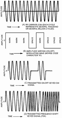
Frequency-SHIFT KEYING (FSK) is similar to CW keying in amplitude modulation and is a
form of angle modulation. The carrier frequency is changed between two discrete values by the opening and closing
of a key. 2-53
In Frequency MODULATION (FM) the instantaneous frequency of the radio-frequency wave is
varied in accordance with the modulating signal; the amplitude of the radio-frequency wave is kept constant.
2-54

MODULATION Index is the ratio of the maximum frequency difference between the modulated
and the unmodulated carrier, or between the deviation frequency and the modulation frequency. The number of
SIGNIFICANT SIDEBandS and the modulating frequency will determine the bandwidth of the fm wave. The number of
significant sidebands can be determined from the modulation index. MODULATION Index
SIGNIFICANT SIDEBandS 
The REACTANCE-TUBE Modulator is frequency modulated by using a reactance tube in shunt
with the tank circuit. 2-55

The SEMICONDUCTOR-REACTANCE Modulator is used to frequency modulate low-power
semiconductor transmitters.

2-56
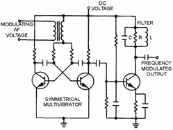
The MULTIVIBRATOR Modulator uses an astable multivibrator with a modulating voltage
inserted in series with the base return of the multivibrator transistors.
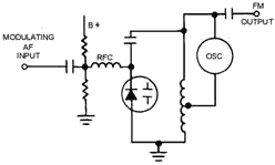
The VARACTOR FM Modulator uses a VARACTOR. This is a specially
designed diode that has a certain amount of capacitance between the junction that can be controlled by reverse
biasing.
In Phase MODULATION the carrier's phase is caused to shift at the rate of the
modulating audio. The amount of phase shift is controlled by the amplitude of the modulating wave. 2-57

A Basic Phase Modulator may be a single tube in series with a capacitor to form a
phase-shift network. As the impedance of the tube changes, the phase of the output shifts. 
Phase-SHIFT KEYING (PSK) is similar to CW and FSK. It consists of phase reversals of
the carrier frequency as modulating signal data elements open and close the modulator key. 2-58

PULSE MODULATION is modulation in which we allow oscillations to occur for a given
period of time only during selected intervals. 
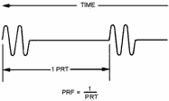
PULSE-REPETITION TIME (PRT) is the specific time period between each group of RF
pulses.
2-59
PULSE-REPETITION Frequency (PRF) is found by dividing the pulse repetition time into
1. This defines how often the groups of pulses occur. PULSE WIDTH (PW) or PULSE
DURATION (PD) is the time that a pulse is occurring. 
REST TIME (RT) is the time referred to as nonpulse time.

PEAK Power is the maximum power during a pulse. AVERAGE Power
equals the peak power averaged over one complete cycle. DUTY Cycle is the ratio of
working time to total time, or the ratio of actual transmit time to transmit time plus rest time, for
intermittently operated devices. The SPARK-GAP Modulator consists of a circuit for
storing energy, a circuit for rapidly discharging the storage circuit, a pulse transformer, and a power source.
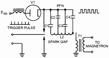
The THYRATRON Modulator is an electronic switch which requires a positive trigger of
only 150 volts. The trigger must rise at the rate of 100 volts per microsecond to fire or cause the modulator to
conduct. 2-60
| - |
Matter, Energy,
and Direct Current |
| - |
Alternating Current and Transformers |
| - |
Circuit Protection, Control, and Measurement |
| - |
Electrical Conductors, Wiring Techniques,
and Schematic Reading |
| - |
Generators and Motors |
| - |
Electronic Emission, Tubes, and Power Supplies |
| - |
Solid-State Devices and Power Supplies |
| - |
Amplifiers |
| - |
Wave-Generation and Wave-Shaping Circuits |
| - |
Wave Propagation, Transmission Lines, and
Antennas |
| - |
Microwave Principles |
| - |
Modulation Principles |
| - |
Introduction to Number Systems and Logic Circuits |
| - |
- Introduction to Microelectronics |
| - |
Principles of Synchros, Servos, and Gyros |
| - |
Introduction to Test Equipment |
| - |
Radio-Frequency Communications Principles |
| - |
Radar Principles |
| - |
The Technician's Handbook, Master Glossary |
| - |
Test Methods and Practices |
| - |
Introduction to Digital Computers |
| - |
Magnetic Recording |
| - |
Introduction to Fiber Optics |
| Note: Navy Electricity and Electronics Training
Series (NEETS) content is U.S. Navy property in the public domain. |
|


