|
January 1947 Radio-Craft
 [Table of Contents] [Table of Contents]
Wax nostalgic about and learn from the history of early electronics.
See articles from Radio-Craft,
published 1929 - 1953. All copyrights are hereby acknowledged.
|
Part II of the "Antenna
Principles" series of article in Radio-Craft magazine discusses
multi-element, long-line, and rhombic antennas. Without burdening the reader
with complicated formulas, the authors introduce many types of antenna
structures and rely on sketches and photos, along with graphs showing radiation
patterns to explain the strengths and weakness of designs relative to each
other. If you are new to antenna construction and operation, these articles
are as a good starting place as any other tutorial. Of course the nice thing
about these days is if you desire to delve deeper into the subject, the Internet
has a plethora of information for learning as much as you care to ingest, and
many online calculator exist for assisting in design of your own antenna.
Part II of
this "Antenna Principles" series appeared in the January 1947 issue,
Part III in
February, Part IV in March,
Part V
in April, and Part VI in the May 1947. I do not yet have Part I from the December 1946
issue.
Antenna Principles - Part II - Multi-Element, Long-Line and Rhombic Antennas
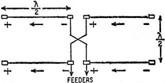
Fig. 1- A simple array, the Lazy-H antenna.
The half-wave dipole antenna is the basis for practically all other types. As
used here, the term "half-wave" refers to an electrical half-wave, not the physical
length. It is the distance which a wave can travel in empty space in the time required
for half of a complete cycle. In space, a half-wave is conveniently calculated from
the equation:

where 300 is the velocity (in millions of meters) of light and radio waves. The
velocity of a wave is less along a solid conductor than it is in space, and along
a conductor of large diameter or cross-section, it is less than on a thin wire.
In many cases the actual physical length must be found by experiment. The velocity
of propagation along coaxial cables is often specified by the manufacturer. Inserting
this information into the above equation (instead of 300) the physical half-wave
may be determined.
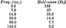
The length of an antenna made of No. 12 or 14 wire will be approximately 95 percent
of that indicated above. Typical antenna lengths are listed below:
Multi-Element Arrays
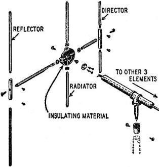
Fig. 2 - Construction of six-element antenna.
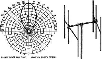
Fig. 3 - The complete antenna of Fig. 2 with a radiation pattern
showing its directivity. Courtesy Workshop Associates, Inc.
The simple dipole can be improved upon by using elements in combination so that
each adds to the effectiveness of the others. In combining elements they must be
driven in proper phase so that power is strengthened in the desired direction and
weakened or cancelled out in other directions. As a result the same power fed into
the array will give a tremendous increase in sensitivity in a given direction, and
at the same time will cut down interference caused by radiating power where it is
not needed. Conversely, as a receiving antenna, sensitivity is decreased from directions
from which no signals are desired. If the entire array can be made to rotate, any
direction may be chosen as the ant of maximum sensitivity.
A common array is shown in Fig. 1 This illustrates the principles of phasing
each antenna so that radiation is strengthened in the desired direction and cancelled
out in others. It consists of four half-wave antennae, two of them forming a straight
line a half wavelength above the other pair. The feeders may (or may not) be of
the resonant type. Polarity signs are drawn for a particular instant of time. It
is evident from the figure that they are fed in phase, that is, current (shown by
arrows) in each flows in the same direction at every instant. This pair acts just
like a single antenna twice as long as the usual dipole, and therefore gives and
receives a stronger signal at right angles to its length.
Since the upper antenna is an electrical half-wavelength above the lower wire
the polarity along the feeder is reversed, but since the feeder is also transposed,
the polarity at corresponding points is the same as that along the lower wire. As
a consequence, radiation is greatly increased (a power gain of about four) broadside
or at right angles to the plans of the antenna, that is, in and out of the page.
On the other hand, waves traveling up or down are cancelled out. Assume, for example,
that the lower wire radiates a positive wave at a particular instant. It reaches
the upper wire just in time to combine with the negative wave which the latter transmits
at that time. The two cancel completely. This antenna array is an example of a driven
system, that is, one in which each element is supplied with power from the feeder
system.
Power may be strengthened in desired directions by elements which are not connected
to the feeders. These elements are known as parasitic. They are designed to pick
up power from the actual driven or radiating element, and to transmit it in the
proper phase so that the resulting wave is either weaker or stronger, as desired.
In the first case, the element is a reflector and is placed behind the radiator.
In the second case, the element is a director, built in front of the radiator. Parasitic
elements are much more convenient to construct both from the standpoint of physical
design and feeding problems. If the distance between elements and the length of
the parasitic elements can be adjusted, optimum results may be obtained by actual
experiment.

Fig. 4 - The "J" antenna is employed widely.
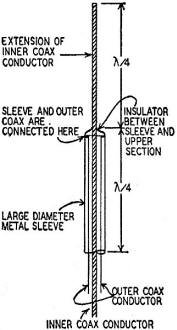
Fig. 5 - Construction of the co-axial antenna.
In general, the reflector is longer than the radiator (which is an electrical
half-wave) and the director is shorter. A difference of about 5 percent in each
case is found to give maximum effects.
The length of a parasitic element varies somewhat with its distance from the
radiator, and the radiation resistance decreases as this distance becomes shorter.
It is usual to build a reflector a quarter wavelength behind the radiator and to
place a director at about 0.1 wavelength in front of it, thus forming a three-element
beam. By rotating the assembly, the beam may be pointed in any direction.
A commercially-designed 146 mc array is shown in Fig. 2. This antenna is made
to be assembled as a six-element beam antenna. The figure shows only one bay, comprising
one radiator, reflector and director. The other three corresponding elements are
located at the other end of the horizontal support. The radiators are fed in phase
from a coaxial cable which is led up the vertical pipe and through each arm of the
horizontal support. Since the two bays are fed in phase, they must be separated
by a half-wavelength.
Each element is made of half-inch aluminum tubing, sealed with spherical tips
on the ends and rigidly supported to withstand wind and ice. This is important if
wobbly signals are to be avoided. The mast can be made rotatable, usually a requirement
for amateur and listener use.
The high power-gain obtained from the six-element beam antenna is illustrated
in Fig. 3. The horizontal plane pattern shows distance vs. angle from the forward
direction of the array. The pattern shows that the signal level say 10 miles from
the array in the forward (0-degree angle) direction can be received at half this
distance, only within a restricted angle of 64 degrees. Outside this angle, the
signal strength is greatly reduced. With this array, a 10-watt transmitter gives
the same output in the favored direction as does 60 watts with a non-directional
radiator.
The simple dipole can be greatly improved and certain of its disadvantages overcome
by using specially designed antennas derived from it.
The J antenna shown in Fig. 4 is a popular one among amateurs. It consists of
a dipole connected to a lower matching section. This section may be considered to
be another half-wave bent to form two parallel conductors. As described in the previous
article, voltage loops appear at each end of a half-wave section and a voltage node
appears at the center. Therefore, high-voltage points are obtained at the upper
ends of the matching section and practically zero voltage at the lower or closed
end. Consequently, the radiator (upper part of the antenna) can be connected directly
to one end of the matching section. Actually, of course, the entire antenna, consisting
of radiator and matching section is made of one piece of heavy aluminum or brass
tubing, or of two parallel conductors connected at their bottom end.
Since the voltage is high at the upper ends of the matching section these points
are at high impedance, while the impedance at the bottom of the J is almost zero.
This means that the entire antenna can be directly grounded or connected to a grounded
mast, thus eliminating insulation and mounting problems. Also, since the impedance
increases gradually from the closed end of the matching section (bottom of the J)
it is evidently possible to find any desired impedance somewhere along the section.
This may be done by experiment.
The feeders must be attached at those points where the ratio of maximum to minimum
voltage along the feeders is as small as possible. It may be determined by use of
a vacuum-tube voltmeter" or an r.f. ammeter moved along the lines. When the voltmeter
or ammeter shows as nearly as possible a constant value all the way down the feeder
lines, the impedance is correctly matched, and maximum output is being obtained.
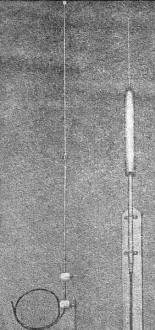
Two types of coaxial antennas. The two illustrated resonate at
approximately 2 meters. Courtesy Engineering Electronics and the Andrew Co.
Coaxial Antenna
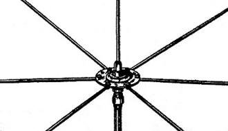
Fig. 6 - High-frequency ground-plane antenna.
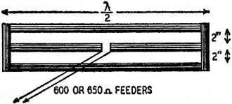
Fig. 7 - A wide-band 3-element folded dipole.
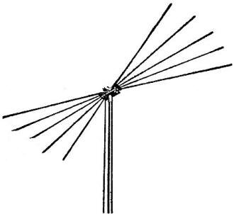
Fig. 8 - A commercial type wide-band antenna.

Fig. 9 - Simple full-wave end-fire "array."
The two conductors of the J matching section are not actually balanced because
one connects to a dipole and the other is left open. Under these circumstances the
two currents cannot be exactly equal in each conductor. Because of this, there is
some radiation from the matching section as well as the dipole, and the reaction
between them distorts the doughnut pattern and may cause power to be radiated upwards.
This is undesirable where local coverage is important, as in police radio and general
amateur work.
The coaxial antenna, designed to eliminate much of this difficulty, is shown
in Fig. 5. It is a combination of coaxial feeder and a dipole antenna. The inner
conductor of the feeder is extended by a quarter-wave and this becomes the upper
half of the dipole radiator. The outer coaxial conductor is connected to a large
diameter sleeve which becomes the lower half of the dipole. The sleeve (like the
upper portion) must be a quarter-wave lone electrically. Because of its wide diameter,
however, its length is generally much less than this physically, and must be determined
by experiment or calculation.
In this antenna, fields due to the feeders cannot react upon the radiator, sections
due to the grounded shield of the coaxial cable. In addition, the two feeder currents
are balanced, one feeding the upper conductor and the other feeding the sleeve.
As a result, there is practically no high-angle radiation from this antenna and
it is an efficient type.
Ground Plane Antenna
High-angle radiation of power can also take place from the earth. This can be
eliminated by cancelling out all downward radiation so that none can be reflected
upwards. A ground plane right below the antenna can be introduced for this purpose.
Fig. 6 shows such an antenna. Electrically, it is a quarter-wave vertical radiator
mounted on an insulator and fed by the inner coaxial conductor. The outer conductor
feeds the ground plane, which is made of either four or six spokes or radials which
are mounted on a metal plate. Although these radials do not make a closed plane,
the effect at the very high frequencies is practically the same.
When designed properly, the radiation pattern is circular (or non-directional)
in the horizontal plane, thus assuring a more efficient use of the radiated power.
Downward radiation is prevented, and therefore no reflection upwards is present.
This antenna is easy to construct and install because it needs only one solid support,
which may be combined with the coaxial feeder. Most antenna systems tune sharply
because of their basically high Q. In other words, their reactance is much greater
than their resistance when they are tuned off their resonant-frequency. This works
out well if only one frequency is to be worked either with c.w. or with amplitude-modulated
phone. For F.M. and television, the situation is changed and the technical requirements
are much different. The antenna must be designed to have a more uniform response
for reception or transmission of the wide-range signals.
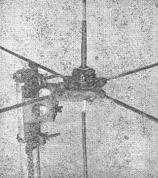
The rods are changed to change frequency.
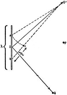
Fig. 10 - Transmission from long-line antenna.

Fig. 11 - The V - an approach to the rhombic.
The simplest wide-band antenna is one which is constructed of relatively large-diameter
tubing. Electrically, this has the effect of reducing the Q. Still better results
are obtained through the use of two or more conductors to form a single antenna
system. A common antenna for this purpose is the folded dipole made of aluminum
or copper tubing (Fig. 7). The figure shows three elements, but any number may be
used. The distance between elements should be very small, a few inches at most,
so that they are effectively in parallel at the frequency of operation.
Another great advantage of the folded dipole is the increase of impedance which
is obtained at the point of feed. For two elements the impedance is 300 ohms and
for three it is 650 ohms. These are values often used for transmission lines, therefore
connection may be made directly to the antenna. Commercial types of wide-band antenna
systems are now beginning to appear on many roofs. Fig. 8 shows one type known as
the "Di-fan"*. It uses five elements extending in several directions and fed by
one transmission line. It is designed to be effective over the television band or
the FM band and gives a uniform response over a wide range of frequencies. The antenna
elements are made of aluminum alloy and lie in a horizontal plane.
Long-Line Antenna
The multi-element types of antennas show that improvement can result by using
more than one element. It is also possible to secure better directivity by using
a longer single element than the basic dipole itself. However, the phase between
elements must be considered.
Let two half-wave elements (Fig. 9) be connected directly to each other. If the
free end of A is negative as marked, the other end of it must be positive at the
same instant. Also, if the inner end of B is positive, its free end must be negative.
Then electrons move from the two open ends towards the center of the long antenna.
The fields radiated by such out-of-phase currents are equal and opposite. No signal
can be received at right angles to such an antenna.
See Fig. 10. P represents a station at right angles to the antenna and Q is another
station making an angle with the full-wave antenna. As shown in the above discussion
P will hear nothing because the fields from each half of the antenna are equal and
opposite at this point. If Q is located at such a point that it is half a wavelength
further from b than it is from a, this station will hear a loud signal from the
transmitter. At a given instant, assume that a positive wave is radiated from a
and a negative from b (since the currents at these points are out of phase). When
the wave from b reaches point c (half a wavelength distant) a negative wave is being
radiated from a. Note what happens. There are two negative waves moving at once
towards station Q and they reach it at the very same time. Evidently, maximum radiation
is in this direction and there is none towards P. It is found that the angle Θ is
about 50°. The same reasoning shows that another station Q' will also receive a
strong signal. Further, if the antenna is, still longer, say two wavelengths, there
will be four lobes, that is, four distinct directions of maximum radiation. In general,
there is an added lobe for each half-wave. Note that the radiation in Fig. 10 takes
place at an angle Θ all around the antenna. The actual solid three-dimensional pattern
is made by the lines DQ and DQ' swinging completely around the antenna.
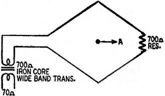
Fig. 12 - The rhombic antenna is good at high frequencies where
its size is not excessive.
The several lobes which are associated with long wires are generally disadvantageous.
More often better efficiency results when only a single lobe is radiated or if the
antenna is made non-directional altogether. Undesired lobe patterns may be eliminated
in two ways: either they may be combined so that some are cancelled and others are
strengthened; or the effects of the out-of-phase antenna currents may be eliminated.
V and Rhombic Antenna
The first method requires the use of two long-wire antennas which make up a V
shape. While this type of antenna is not as popular among amateurs or listeners,
it will be briefly described. Its chief disadvantage is the large area which is
required. In addition, its construction is generally far beyond the abilities of
the average operator.
Fig. 11 shows what happens when two full-wave conductors are joined to form a
V. Radiation along the directions A and B is strengthened so that a strong signal
will be heard by stations located along these lines. The radiation along C and D
is cancelled.
A combination of two V antennas makes a rhombic antenna. The rhombic is also
directional along A and B (Fig. 11). This antenna can be made unidirectional by
closing its far end with a non-inductive resistor. When properly matched (about
700 ohms is required) the standing waves along the antenna are eliminated and communication
can be carried on only in the direction A. The resistor must be capable of dissipating
half of the power fed into the antenna. See Fig. 12.
* The Andrew Co.
Posted June 26, 2020
|


