|
July 1969 Electronics World
 Table of Contents
Wax nostalgic about and learn from the history of early electronics. See articles
from
Electronics World, published May 1959
- December 1971. All copyrights hereby acknowledged.
|
 It appears
that maybe Abraham Lincoln had a son who was an electrical engineer working at Motorola
Semiconductor back in the 1960's. Put glasses on Honest Abe (I did) and author Irwin
Carroll's a spitting image of the Great Emancipator. Seriously though, this article
is a great introduction to the fabrication and use of variable capacitance (aka
varicap and varactor) diodes. They have been - and still are - used widely for electrically
tunable oscillator and filter circuits. Topics such as temperature and figure of
merit ("Q") are discussed as well. It appears
that maybe Abraham Lincoln had a son who was an electrical engineer working at Motorola
Semiconductor back in the 1960's. Put glasses on Honest Abe (I did) and author Irwin
Carroll's a spitting image of the Great Emancipator. Seriously though, this article
is a great introduction to the fabrication and use of variable capacitance (aka
varicap and varactor) diodes. They have been - and still are - used widely for electrically
tunable oscillator and filter circuits. Topics such as temperature and figure of
merit ("Q") are discussed as well.
This edition of Electronics World ran a series of diode articles:
Hot Carrier
Diodes,
Variable-Capacitance Diodes,
Tunnel Diodes,
Microwave
Power Diodes,
A Survey of Silicon Junction Diodes, and
Light-Emitting
Diodes.
Variable-Capacitance Diodes

For the past three years the author has been responsible for
disseminating technical information about Motorola products and developments. In
this capacity he has worked with research engineers, production engineers, application
groups, and product marketing personnel. Prior to joining the company, he worked
for Ameco, Inc., preparing training material on use and maintenance of CATV equipment.
By Irwin Carroll / Supervisor
Technical Communications, Motorola Semiconductor Products Inc.
Diodes whose junction capacitance is variable with voltage are beginning to replace
large bulky tuning capacitors. Here are the operating principles and important parameters.
Varactor diodes, or variable-capacitance diodes, are semiconductor diodes that
have been optimized for the capacitance effect under reverse-bias conditions. Basically,
they can be divided into two main applications categories: tuning and harmonic generation.
As might be expected, they have different characteristic requirements, but do share
the common trait of having a junction capacitance that is variable with voltage.

Fig. 1 - Behavior of depletion region under various bias
conditions. The most commonly used symbols are shown.
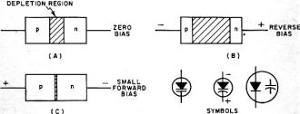
Fig. 2- Equivalent circuits for a varactor diode.
The capacitance effect in a varactor arises from the depletion region separating
the p and n material in a diode. Recalling simple junction physics, the depletion
region has a high resistivity because of the lack of mobile carriers and, as such,
makes a good dielectric. When a reverse bias is applied to the diode, the depletion
region is widened and if slightly forward-biased (not enough to cause forward conduction),
the depletion region narrows. Fig. 1 is a simplified diagram of how bias affects
the junction. The p- and n-doped regions are the "conductive plates" and, of course,
the closer the plates of a capacitor, the higher the capacitance value, so that
at zero, or slightly forward bias, the maximum capacitance value is reached. The
minimum capacitance occurs when the depletion region is widest - at reverse breakdown
voltage.
Used as a tuning diode, a varactor is biased between zero voltage and reverse
breakdown voltage. (Actually parametric amplifiers would also fall into this category
but will not be discussed in this article.) The equivalent circuit for a varactor
diode is given in Fig. 2A. For low-frequency operation, the circuit reduces
to that of Fig. 2B.
Doping profiles of varactors vary according to their intended use. Fig. 3
shows the four most common types encountered. The abrupt and hyper-abrupt junctions
are used for tuning while the linearly graded and step-recovery junctions are used
for harmonic generation. The abrupt junction can also be used for harmonic generation,
but because the second harmonic predominates, it is impractical for high harmonics.
The step-recovery diode is a departure from the normal varactor since the capacitance
change is quite small and occurs mostly near zero bias. Also, the step-recovery
device makes use of forward bias and charge storage. The phenomenon that occurs
is not too different from the reverse-recovery action of a common rectifier diode.
Simply stated, when the junction is slightly forward biased, charge carriers from
one region are injected into the other to form minority carriers in that area. If
the lifetime of the carriers is longer than the period of the applied forward voltage,
when the reverse voltage is impressed across the junction, most of the carriers
are returned to their point of origin in a compact bunch. While the carriers are
returning, there is a high reverse current flowing; when they reach their point
of origin, the current flow ceases abruptly.
The steep current waveform generated is rich in harmonics and when added to the
other non-linearities of the varactor enhances its multiplier function. Step-recovery
varactors have been used to obtain useful output levels for frequencies as high
as the 25th harmonic of the input. Such devices are very economical when it is necessary
to obtain crystal-controlled frequencies in the microwave region. Other devices
can produce as much as a watt of power in the 12-GHz region (doubling from 6 GHz).
Tuning Applications
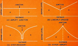
Fig. 3 - Doping profiles for various varactor diodes.
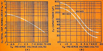
Fig. 4 - (A) Normalized curve of capacitance vs reverse
voltage for abrupt-junction diode. (B) Typical capacitance vs reverse voltage for
the hyper-abrupt diodes.
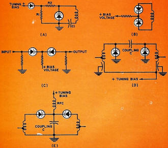
Fig. 5 - (A) Varactor-tuned circuit with diode for temperature
compensation. (B) Using diodes back-to-back to reduce intermodulation distortion.
(C) Varactors used as variable coupler. (D) Double-tuned circuit using parallel
resonance. (E) Same but using series resonance.
As a variable capacitor, the varactor is rugged and small, is not affected by
dust or moisture, and is ideal for remote control and precision fine tuning. The
current uses of tuning diodes span the spectrum from AM radio to the microwave region.
Presently the cost of varactor tuning is a little higher than conventional methods
but the cost is coming down quite rapidly as sales volume increases.
The most significant parameters of a tuning diode are the capacitance ratio,
"Q", series resistance, nominal capacitance, leakage current, and breakdown voltage.
For high-frequency operation, the package parasitics are also important considerations.
The capacitance ratio, which defines the tuning range, is the amount of capacitance
variation over the bias voltage range. It is normally expressed as the ratio of
the low-voltage capacitance divided by the high-voltage capacitance. For example,
a typical spec which reads C4/C60 = 3 indicates that the capacitance
value at 4 volts is 3 times the capacitance value at 60 volts. The high voltage
in the ratio is usually the minimum breakdown voltage specification. A 4-volt lower
limit is quite common since it describes the approximate lower limit of linear operation
for most abrupt-junction devices.
The curve in Fig. 4A is a normalized bias vs capacitance relationship for
abrupt junctions and if the capacitance at a given reverse bias is known, the capacitance
at other voltages can be determined. This curve follows the relationship:
 ............ (1) ............ (1)
where: CT = total capacitance, Cc = case capacitance (about
0.17 pF for glass diodes), C0 = junction capacitance at zero bias, VR
= reverse bias voltage, φ = contact potential (about 0.6 V for silicon) , and γ
= power law of the junction (determined by doping gradient and is approximately
0.45 for abrupt junctions).
The capacitance ratio of tuning diodes varies in accordance with construction.
Diffused tuning diodes are usually limited to a 4:1 capacitance ratio; alloy types,
5:1; and hyper-abrupt junctions can have ratios of 20:1 and higher.
The hyper-abrupt diode, because of its doping gradient (see Fig. 3D) , has
a γ ≈ 2. A typical bias vs capacitance curve for this type of diode
is shown in Fig. 4B. Particular effort has been devoted to this type of diode
because of its high capacitance ratio potential. Indeed, it is the only type suitable
for tuning the AM broadcast band, which requires a minimum tuning ratio of 10:1.
Temperature Stability & Figure of Merit
The temperature stability of a tuning diode is related to contact potential, φ
As shown in Eq. (1), temperature effects will be greatest at low values of reverse
bias and will become minimal for high values of VR Changes in φ of
1.5 to 2.7 mV/°C are typical. This variation can be compensated, if necessary,
by using a silicon diode with the same temperature coefficient in the bias supply,
as shown in Fig. 5A.
The figure of merit or "Q" of a tuning diode should be specified at a given reverse
bias and frequency. However, rather than stating "Q", series resistance at a given
bias might be more practical. As shown previously in Fig. 2, RS
is in series with CJ but RS is also variable with bias, decreasing
in value as bias voltage increases. The "Q" for a capacitor with a series resistance
is given by:
Q = 1 / (2πfCRS) ..........(2)
where: f = frequency in Hz, C = capacitance in farads, and RS
= series resistance in ohms.
As reverse bias increases, both C and RS decrease, so that at a given
frequency, "Q" is greatest n t the highest reverse bias. For example, a diode that
has a "Q" of 500 at 50 MHz and 2 volts reverse bias could have a "Q" of 2000 at
the same frequency and 20 volts reverse bias. With this relationship in mind, if
a tuned circuit is designed so that the highest frequency corresponds with a bias
voltage that is at or near the maximum operating point, "Q" will be greatest at
the highest frequency. Since selectivity is a function of "Q", selectivity will
also he highest at the high end of the operating band.
Ideally, tuning diodes should have high "Q", low series resistance, low reverse
leakage, and high breakdown voltage at any desired capacitance ratio; however, as
might be expected, these parameters are not unrelated and improving one degrades
another so that often a compromise must be reached. As a rule, diodes with low capacitance
values have the highest "Q" and where this is the most important parameter, as in
the high-selectivity tuners, the smallest possible capacitance value diode should
be used. If large variations in operating temperature are expected, and temperature
stability is the greatest need, large capacitance values should be chosen so that
bias voltage can be kept at a high level.
Circuit Considerations
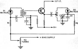
Fig. 6 - AM radio front-end using varactor-diode tuning.
One of the simplest forms of varactor-tuned circuit was shown in Fig. 5A
(with the compensating diode and R1 removed). Capacitor C1 is used for d.c. blocking
and R2 (several hundred kilohms) provides isolation. However, in some applications
the a.c. swing in the circuit might cause intermodulation distortion. Two things
can be done to minimize this effect: (1) the a.c. signal should be as small as possible,
and (2) a back-to-back pair of tuning diodes can be employed.
In the first case, for a given power level, low-impedance circuits have lower
voltage swings - and voltage is the tuning mechanism; however, to maintain high
"Q", the L/C ratio should be as small as possible. Fig. 5B is an example of
the back-to-back diode method of reducing intermodulation. Note that the d.c. blocking
capacitor is no longer necessary. This particular configuration is also useful as
a variable coupling capacitor, as shown in Fig. 5C.
When operating at very high frequencies, the diode inductance, which has been
ignored thus far, must be taken into account. As an example, the double-tuned, parallel-resonant
circuit shown in Fig. 5D is useful at relatively low frequencies but has serious
limitations at frequencies high enough for the diode inductance to become effective.
Fig. 5E shows a double-tuned, series-resonant circuit where the diode inductances
simply add to the circuit inductances and so do not degrade performance. By using
series-resonant techniques, varactors have been successfully applied to the tuning
of microwave cavities.
The development of hyper-abrupt junction diodes, with their high tuning ratios
suitable for AM radio tuning, has stimulated a new and higher interest in such devices.
This is particularly true because of the many advantages they present for car radios
which can be unhitched from their normal dash-mounted positions and placed in more
easily accessible locations.
Fig. 6 shows the front-end of an AM radio modified for electronic tuning
by means of varactor diodes. In this application, or any other where two or more
stages are tuned simultaneously, matching of the diodes is important if the stages
are to track one another. This means that the voltage vs capacitance curve for the
diodes must be nearly the same. For the circuit in Fig. 6, a tracking error
of up to 2 percent provided good results. By adding a ramp-voltage circuit and search
oscillator to the circuit, search-tuning becomes a compact possibility. The frequency
can be monitored by a voltmeter (measuring the bias voltage) calibrated in terms
of frequency. Precision tuning can be achieved by using a multi-turn potentiometer
in the bias supply.
Another obvious application for tuning diodes is for frequency modulation. The
circuit of Fig. 7 has a center frequency of 52 MHz with a frequency deviation
of ±75 kHz. Voltage input, ΔV, is limited to ±200 mV
with the polarity chosen so that a positive ΔV corresponds to an increase
in the diode reverse-bias voltage.
Other Circuit Applications

Fig. 7 - A frequency modulator using a varactor diode.
Step-recovery varactors are commonly used for high-order harmonic generation.
Typical efficiencies may run around 30 percent for an 8X multiplication down to
around 10 percent for a 25X multiplication.
The step-recovery diode can be used to great advantage as a duplexer, permitting
a single antenna to be used for both transmitting and receiving. Normally, p-i-n
varactors are used for this application but have the disadvantage of requiring an
external bias circuit.
In multiplier applications, the power dissipation of the varactor becomes an
important consideration. Also, the efficiency, η, defined as Pout/Pin
is important. The latter is highly dependent on the multiplying factor, being as
high as 75 percent for doubling and dropping to 10 percent for X25.
Future Growth
Although the cost of varactor tuning is slightly higher than mechanical methods,
the advantages gained are usually well worth the difference. Compact, reliable,
and what would be otherwise impractical circuits have been developed with tuning
diodes. Gallium-arsenide tuning diodes for parametric amplification cost as much
as $400, silicon devices for u.h.f. and microwave tuning, $12; matched sets of hyper-abrupt
junction diodes for AM tuning, less than $3 each, and plastic encapsulated diodes
for tuning and a.f.c. applications in the v.h.f. TV and FM areas, less than $0.40
each. (These are all small-quantity prices; however, as usage, hence volume, increases
the price will drop to very competitive levels.)
Varactors for harmonic generation can cost from $20 to $150 with several high-quality
units (up to 12-GHz operation) costing less than $60. New devices such as Gunn-effect
and IMPATT diodes and higher frequency transistors are reducing the need for some
types of varactors but usage continues to grow. Two important areas of this growth
are duplexing and digital phase shifting.
|


 It appears
that maybe Abraham Lincoln had a son who was an electrical engineer working at Motorola
Semiconductor back in the 1960's. Put glasses on Honest Abe (I did) and author Irwin
Carroll's a spitting image of the Great Emancipator. Seriously though, this article
is a great introduction to the fabrication and use of variable capacitance (aka
varicap and varactor) diodes. They have been - and still are - used widely for electrically
tunable oscillator and filter circuits. Topics such as temperature and figure of
merit ("Q") are discussed as well.


 ............ (1)


