Module 21 - Test Methods and Practices
Pages i ,
1-1,
1-11,
1-21,
2-1,
2-11,
2-21,
2-31,
2-41,
3-1,
3-11,
3-21,
3-31,
4-1,
4-11,
5-1,
5-11,
5-21,
5-31, AI-1 to AI-3, Index
5. Have overvoltage
protection 6. Be small, light, and easy to handle 7. Have a high input impedance to protect
against circuit loading Q-23. What is the purpose of a logic probe? LOGIC PULSERS
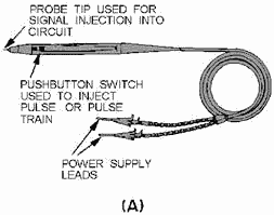
Another extremely useful device for troubleshooting logic circuits is the logic pulser. It is similar in
shape to the logic probe and is designed to inject a logic pulse into the circuit under test. Logic pursers are
generally used in conjunction with a logic clip or a logic probe to help you trace the pulse through the circuit
under test or verify the proper operation of an IC. Some logic pursers have a feature that allows a single pulse
injection or a train of pulses. Logic pursers are usually powered by an external dc power supply but may, in some
cases, be connected directly to the power supply of the device under test. View a of figure 2-27 shows a typical
logic pulser. View B shows a logic pulser (right) used with a logic probe
..................
Figure 2-27A. - Logic pulser.
2-31
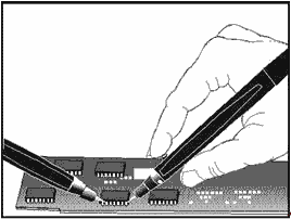
Figure 2-27B. - Logic pulser. LOGIC ANALYZER A relatively new device on the test equipment scene is the logic
analyzer. a logic analyzer provides various functions that can assist you in maintenance, testing, and
troubleshooting of equipment using digital circuitry. From your standpoint, they are extremely useful in
performing timing analysis. Most logic analyzers have CRT displays that can monitor up to 32 timing signals at the
same time. a large percentage of today's digital equipment is designed with the logic analyzer in mind and have
built-in status or bus lines for your convenience in monitoring multiple signals at the same time. When monitoring
a bus line, you can readily determine, through visual displays, such things as the presence of master clock
signals or sequential timing events.
BATTERY MEASUREMENTS As a technician, you are primarily concerned with the uses of batteries; however, checking or testing of
storage and dry cell batteries is an important part of your maintenance program. Proper preventive maintenance of
batteries can significantly extend the useful life of a battery. STORAGE BATTERIES
When you check a lead-acid type of storage battery for its condition of charge or discharge, you take a specific
gravity reading of the electrolyte by using a hydrometer. a specific gravity reading between 1.275 and 1.300
indicates a full-charge condition and assures you that the battery is in good condition. A hydrometer reading
of approximately 1.175 indicates a normal discharge condition, and a reading of approximately 1.250 indicates that
the battery is half-discharged. Since the acids used in various batteries do not always have the same specific
gravity and since electrode composition may differ, the hydrometer reading you obtain at the charged and
discharged conditions will vary with the type of electrolyte and battery composition. a general rule for you to
follow is not to discharge a battery more than 100 points (.100 specific gravity) before recharging.
Although readings of specific gravity are a reliable measure of the condition of a storage battery, cells that
indicate normal may prove useless under load. This is usually caused by a high internal resistance. a load-voltage
check of the cells with the use of a cell tester indicates the actual voltage
2-32
charge held by each battery cell. Cell voltages should not differ by more than 0.15 volt for 6-volt or
12-volt batteries. Use extreme caution whenever testing or working around lead-acid storage batteries.
OPNAVINST 5100.23B emphatically states that you must wear eye protection devices at all times and that emergency
eyewash facilities must be immediately adjacent to, or within 10 feet of, any eye-hazard area. Smoking and
spark-producing tools or devices are also prohibited in enclosed spaces that contain lead-acid storage batteries.
When charging, these batteries produce sufficient quantities of hydrogen to produce large explosions. Lead-acid
storage batteries should only be charged in well-ventilated spaces. Q-24. Emergency eyewash facilities
must be located within what minimum number of feet of an eye- hazard area? DRY BATTERIES You must periodically check dry cell batteries that are used for test
instruments and portable or field equipments for loss of power. For actual voltages of dry batteries, you should
measure with a battery tester for a minimum acceptable voltage before installation. The TS-183/U series of battery
testers incorporate a multiple-range voltmeter, battery-loading resistors, multiplier resistors, and a
jack-switching arrangement that connects the load resistors across the voltmeter for a total of 32 different
voltmeter-load resistor combinations. This type of tester permits you to complete a rapid and accurate measurement
of battery potentials under load conditions, ranging in voltages from 1.5 to 180 volts. a data chart supplied with
the battery tester provides information regarding the jack to be used and minimum acceptable voltages of various
batteries used in Navy equipments. Q-25. What is the advantage of using a battery test set versus a
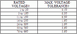
voltmeter to test batteries? Table 2-2 shows general standards of tolerance for dry batteries. Whenever
practical, dry cell batteries that are not in use should be stored in a refrigerated area to extend their shelf
life.
Table 2-2. - Typical voltage Tolerances for Dry Cell Batteries
 CARBON-ZINC and ALKALINE BATTERIES Carbon-zinc and alkaline cells are used
primarily in portable test equipment, VOMs, flashlights, some portable radios, and beacon equipment. The
carbon-zinc cell provides 1.5 volts and holds its charge for approximately 1 year in normal service. The alkaline
cell provides 1.2 volts and has about twice the stored energy of the carbon-zinc cell of the same size. It also
has a longer life at a higher discharge rate than the carbon-zinc cell. You should discard both types of batteries
at the first indication of weakness.
2-33
MERCURY CELLS The storage life of a mercury cell varies but is generally
classified as long. The working life of the cell is extremely long relative to other types of batteries; and it
maintains its full rated voltage (1.34 volts) until just before it is ready to expire, at which point its voltage
will drop off sharply. Recharging of mercury cells is possible, but is not recommended because the recharging
cycle can vary from one cell to another; and, after being recharged, their operating lifetime is uncertain.
NICKEL-CADMIUM BATTERIES (NICAD) Nickel-cadmium batteries have very high efficiency. They can be
recharged hundreds of times; given the proper conditions, they may even be recharged thousands of times. They can
be stored for a number of years with no significant loss of performance. After just a few charge and discharge
cycles, NICAD cells can be recharged to the point that they are just as good as new batteries. Since they are
sealed, they are maintenance free and can be installed in any position. There are two types of nickel-cadmium
batteries - vented and non-vented. This description deals with the non-vented exclusively because a vented NICAD
would have extremely limited application in a shipboard environment. The voltage at the terminals of a
NICAD will normally be between 1.25 and 1.30 volts in an open- circuit condition. This value will vary, of course,
depending on the state of charge. If the charge has dropped to a low of 1.1 volts, the NICAD should be regarded as
being completely discharged and should not be permitted to be discharged further. The majority of small NICADs are
rated in milliampere hours; the large ones are rated in ampere hours. The small NICAD is the one the technician
will almost always be concerned with. Q-26. At what voltage is a NICAD battery considered to be fully
discharged?
As a general rule, if the charging current is held to 10% of the milliampere-hour rating for the NICAD and the
time of charge is held at 150% of the time required to establish its full milliampere-hour rating, you will
encounter no difficulty in maintaining NICADs at their maximum charge. For example, you should charge a battery
rated at 300 milliampere hours for 15 hours at 30 milliamperes. You can leave the battery on extended charge for
years, provided the charge rate is lowered to less than 10% of the NICAD's milliampere rating. You should
never place a NICAD in your pocket, because metal objects (such as keys) can short the cell and cause extreme
heat. Never dispose of a NICAD by fire, because it can explode. Never solder a connection directly to the cell,
because the heat of an iron can damage it. Never overcharge a NICAD cell, because an accumulation of gases within
its case can destroy it. NICADs are also subject to a phenomenon commonly referred to as cell memory. If a
NICAD is consistently discharged to a minor extent (for example, 30 minutes per day) and then recharged after each use, the useful capacity of the cell will eventually be reduced to that level. To keep this from happening, you
should fully discharge (1.1 volts) NICADs on a regular basis. In fact, some maintenance requirement cards and
calibration laboratory procedures require this periodic full discharge of equipment containing NICADs.
RF ATTENUATORS and RESIsTIVE Load TESTS All RF attenuators, decade or step attenuators, decade resistors, and 50/75-ohm loads are clearly marked
to show their attenuation factor or resistance. In the case of precision RF attenuators, they are usually marked
to show their useful frequency ranges. They are all basically resistive devices and are
2-34
designed for a multitude of applications. None of these devices are user-repairable; however, you
should be aware of the different methods of determining whether or not they are functioning properly.
FIXED RF ATTENUATORS Fixed RF attenuators (shown in fig. 2-28), such as the ones commonly
found in power-measuring sets, are designed to provide a fixed-signal attenuation over a specific frequency range.
Frequency ranges can be in excess of 30 gigahertz, and attenuation factors are typically in 1-, 3-, 6-, and 10-dB
steps. Fixed attenuators can be connected in series to provide you with the desired attenuation. Most fixed RF
attenuators are designed to handle only small amounts of RF power and are extremely susceptible to damage because
of overloading. To test a fixed RF attenuator, you can either substitute it with a known good attenuator or
perform basic measurements on the attenuator itself. With the RF substitution method, you connect an RF signal
generator to a power meter and establish a suitable reference point on the meter by adjusting the power output of
the signal generator. Once you establish the reference point, insert the RF attenuator between the signal
generator and the power meter. You then determine the attenuation by noting the difference between the power meter
reading and the initial reference point.

Figure 2-28. - Fixed attenuator set. Q-27. What is the most common method of testing a fixed RF attenuator?
DECADE ResistorS Decade resistors (also referred to as decade boxes) typically are
precision devices. Depending on the make and model of the decade resistor, it may be capable of providing you with
a selection of resistors ranging in value from a small fraction of an ohm to hundreds of megohms. Decade resistors
are commonly used in calibration laboratories and in engineering design applications. Like the fixed RF
attenuator, most decade resistors are capable of handling only small amounts of current. They are very limited in
respect to frequency capabilities and are commonly used in dc-circuit applications. You may encounter specific
equipment that requires the use of a decade resistor in performing your maintenance tests or alignments. To test a
decade resistor, you can connect a standard multimeter or digital multimeter directly across its resistance
terminals and read its resistance on the meter. This test will only indicate gross errors in the decade resistor
such as an open or a badly damaged resistor. If you are performing a precision measurement or an alignment using a
decade resistor and have any doubt as to its accuracy, you should submit it to your servicing calibration
laboratory. Figure 2-29 shows a typical decade resistor.
2-35

Figure 2-29. - Decade resistor. DECADE (STEP) ATTENUATORS Decade attenuators (also referred to as step
attenuators) are common devices that may be designed as either a stand-alone piece of test equipment or as an
integral part of an operational piece of electronic equipment. As the name implies, they are used to attenuate RF
signals in incremental steps. Like the fixed RF attenuator, you can easily test them by using the RF substitution
method, as previously described. Views a and B of figure 2-30 show two types of decade attenuators.
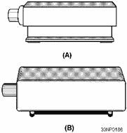
Figure 2-30. - Step attenuators. 50/75-OHM TERMINATIONS Terminations of 50 and 75 ohms are designed as either
feedthrough, impedance-matching devices, or as RF loading devices. They are precision resistors sealed in small
plastic or metal enclosures and are designed to be mounted on various RF connectors. In the case of feedthrough
terminations, they are designed with RF connectors at both ends, which allows the RF signal to pass through them.
They are impedance-matching devices designed primarily to reduce the voltage standing-wave ratio (vswr) that is
produced when two pieces of equipment with dissimilar impedances are connected together. You can test a
feedthrough termination by measuring the resistance between the center conductor and the shield of either RF
connector with an ohmmeter. As mentioned above, some terminations are manufactured as loading devices that are
designed to shunt an RF signal to ground. a perfectly matched termination can be compared to a transmitting
antenna in that it absorbs all of the RF signal with only a
2-36
small amount of power being reflected back to the transmitting device. When using a termination as a
load, you should ensure that its wattage rating exceeds the power output of the equipment to which it is
connected. You can also measure this type of termination by using a standard ohmmeter to read the resistance
between the center conductor and the shield of the RF connector. Q-28. What is the most common method
of testing resistive terminations? Fiber-OPTIC TESTING Fiber optics are
a relatively new type of transmission media. Figure 2-31 depicts a typical fiber-optic cable design. The core of
the fiber-optic cable is the optical transmission path, which carries data from the optical transmitter to the
optical receiver. The core is usually made of plastic, glass, or plastic-clad silica (PCS). Glass-core fibers are
usually smaller in diameter than plastic or PCS cores. The major disadvantages of glass cores are that they have
high attenuation (25 dB/km), require precision tools and connectors, and are extremely susceptible to mechanical
damage. Plastic cores are typically more rugged than other types of cores, but their attenuation is high (35
dB/km). PCS cores are fairly rugged and have a relatively low attenuation (10 dB/km). a fiber-optic cable may
consist of one fiber, multiples of single- optical fibers, or bundles of optical fibers. Fiber-optic cables are
well suited for the transmission of high- speed data over relatively short distances. They are virtually immune to
crosstalk or interference through inductance. (Interference is a characteristic of metallic cables.)
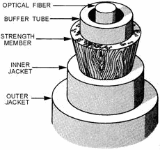
Figure 2-31. - Typical fiber-optic cable. Testing techniques and the principles of measurement for fiber-optic and conventional cable are similar.
For example, if both ends of the cable are exposed and can be used for testing, relatively unsophisticated
equipment can be used to measure cable parameters, such as continuity and attenuation. This includes equipment
such as optical multimeters and optical power meters (OPM). If only one cable end is available, then more
sophisticated equipment such as an optical time-domain reflectometer (OTDR), is used. The following section lists
and defines some common optical test equipment. Q-29. What is the main disadvantage of using
fiber-optic cables?
2-37
OPTICAL TIME-DOMAIN REFLECTOMETER (OTDR) The portable optical time-domain
reflectometer (OTDR) is used to check loss at each splice, at each connector, and of the entire system. Loss
measurements are figured by using the same methods you would use for wire loss measurements. The OTDR injects a
short, intense laser pulse into the fiber and monitors reflections caused by breaks, inclusions, microcracks, and
discontinuities. Discontinuities appear as a spike on the OTDR display. The loss at the discontinuity point is
directly related to the distance between the major pulse triggered by the laser and the spike. The manufacturer's
manual provides you with conversion factors to figure actual losses and locations of the discontinuities.
OSCILLOSCOPE
An oscilloscope is used with an OTDR to provide visual evidence of fiber faults, connector and splice locations,
and attenuation locations. OPTICAL MULTIMETER The optical multimeter measures
light sources and light in cable and at the detector, fiber cable transmission loss, and connector splice loss.
For cable transmission measurements, transmission through a short length of cable is compared with transmission
through a known longer length. OPTICAL OHMMETER The optical ohmmeter measures the
input versus the output of light in an optical fiber. It displays attenuation losses based on a comparison of
known and unknown cable signals. It can be used in manufacturing, connecting, and installing cable. It is as
simple to use as a digital voltmeter. OPTICAL Power METER The optical power meter
measures current by converting light power from plug-in units, such as light emitting diodes, into electrical
current. In some models, the readout is in power units, watts. In other models, the readout is in absolute power
levels and attenuation. Some units operate with a variety of power sensors for conventional coaxial and waveguide
systems and fiber-optic systems. RadioMETER/PHOTOMETER The radiometer/photometer
measures light power in watts from dc to unlimited ac response. It uses plug-in sensor heads and, for low-light
displays, it uses spectrometers and fiber-optic measurements. AUTOMATIC Test Equipment
Automatic Test Equipment (ATE) is test equipment designed to evaluate the operational performance of a piece
of equipment or printed circuit board (PCB). ATE assists you in troubleshooting a fault to the defective
component. Basically, ATEs are state-of-the-art, computer devices in which software programs are specifically
tailored to meet the requirements of the device being tested. The AN/USM-465 Portable Service Processor
(PSP), shown in figure 2-32, is the Navy's standard ATE for testing digital PCBs.
2-38
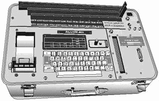
Figure 2-32. - AN/USM-465 Portable Service Processor. The AN/USM-465 is part of the Support and Test Equipment Engineering Program (STEEP). It provides
on-site screen testing and fault isolation of digital PCBs and modules. The PSP is presently available on most
ships and shore intermediate maintenance activities (SIMA) with Mini/Micro maintenance stations (2M). PSPs come
with maintenance-assist modules (spare parts kit) and diagnostic kits. The PSP is easy to use. You have a
choice of three PCB connectors (located on the top panel of the test set) into which you insert the PCB being
tested. The software program, which is provided on magnetic tape cartridges, is then loaded into the test set. The
test set automatically tests the PCB by applying input signals to the appropriate pins while monitoring the output
signal for a correct indication. An LED display will give you a pass or fail indication. If a PCB fails the
operational test, the PSP tells you (via LED display) what troubleshooting steps must be taken. The PSP uses a
guided probe fault isolation technique that tells you what test points to check on the faulty PCB. The software
program guides you from the faulty output backwards toward the input until the fault is located. The probe is a
standard 10 megohm, 10 to 1 oscilloscope probe. The guided probe circuitry and software is also unique because it
is capable of locating faults within feedback loops and can sense when you have placed the probe at an incorrect
test point. An interesting advantage is that if the PSP itself fails, the faulty board inside the PSP can
be identified by the test set's own capability. After you replace the faulty PCB with a good one from the spare
parts kit, you can use the PSP to identify the faulty component on its own PCB. HUNTRON TRACKER
2000 The Huntron Tracker 2000, shown in figure 2-33, is a versatile troubleshooting tool used to
statically test resistors, capacitors, inductors, diodes, transistors, multiple-component circuits, and integrated
circuits. Its built-in features eliminate the use of multiple pieces of test equipment. These features and its
lightweight portability make the 2000 a widely used tool for troubleshooting.
2-39
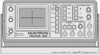
Figure 2-33. - Huntron Tracker 2000. We recommend you review setup and operating procedures discussed in NEETS Module 16, Introduction to
Test Equipment, NAVEDTRA B72-16-00-95, before continuing with this chapter. Since the 2000 was covered in depth in
module 16, we will cover only the most common troubleshooting procedures and provide a few troubleshooting tips.
Q-30. What two features make the Huntron Tracker 2000 a widely used troubleshooting tool?
The Huntron Tracker 2000 has the following features:
· Multiple-test signal frequencies (2000 Hz, 400 Hz,
and 50/60 Hz).
· Four impedance ranges (low, medium 1, medium 2, high).
· Automatic range
scanning.
· Range control: High Lockout.
· Rate-of-channel alteration and/or range scanning
is/are adjustable.
· Dual-polarity pulse generator for dynamic testing of three terminal devices.
· LED indicators for all functions.
· Dual-channel capability for easy comparison.
· Large CRT
display with easy-to-operate controls.
Caution
The device to be tested must have all power turned off, and have all high voltage
capacitors discharged before connecting the Tracker 2000 to the device.
2-40
| - |
Matter, Energy,
and Direct Current |
| - |
Alternating Current and Transformers |
| - |
Circuit Protection, Control, and Measurement |
| - |
Electrical Conductors, Wiring Techniques,
and Schematic Reading |
| - |
Generators and Motors |
| - |
Electronic Emission, Tubes, and Power Supplies |
| - |
Solid-State Devices and Power Supplies |
| - |
Amplifiers |
| - |
Wave-Generation and Wave-Shaping Circuits |
| - |
Wave Propagation, Transmission Lines, and
Antennas |
| - |
Microwave Principles |
| - |
Modulation Principles |
| - |
Introduction to Number Systems and Logic Circuits |
| - |
- Introduction to Microelectronics |
| - |
Principles of Synchros, Servos, and Gyros |
| - |
Introduction to Test Equipment |
| - |
Radio-Frequency Communications Principles |
| - |
Radar Principles |
| - |
The Technician's Handbook, Master Glossary |
| - |
Test Methods and Practices |
| - |
Introduction to Digital Computers |
| - |
Magnetic Recording |
| - |
Introduction to Fiber Optics |
| Note: Navy Electricity and Electronics Training
Series (NEETS) content is U.S. Navy property in the public domain. |
|


