Module 18 - Radar PrinciplesPages
i,
1-1, 1-11,
1-21,
1-31,
1-41,
2-1,
2-11,
2-21,
2-31,
2-41,
3-1,
3-11,
3-21,
4-1,
4-11,
4-21,
AI-1,
AII-1,
Index-1 to 3
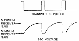
Figure 2-29. - STC voltage waveform. The combination of STC and IAGC circuits results in better overall performance than with either type of
gain control alone. Stc decreases the amplitude of nearby target return signals, while IAGC decreases the
amplitude of larger-than-average return signals. Thus, normal changes of signal amplitudes are adequately
compensated for by the combination of IAGC and STC. Antijamming Circuits Among the
many circuits used to overcome the effects of jamming, two important ones are GATED AGC Circuits and
FAST-TIME-CONSTANT Circuits. a gated agc circuit permits signals that occur only in a very short time interval to
develop the agc. If large-amplitude pulses from a jamming transmitter arrive at the radar receiver at any time
other than during the gating period, the agc does not respond to these jamming pulses. Without gated agc,
a large jamming signal would cause the automatic gain control to follow the interfering signal. This would
decrease the target return signal amplitude to an unusable value. Gated agc produces an output signal for only
short time periods; therefore, the agc output voltage must be averaged over several cycles to keep the automatic
gain control from becoming unstable. Gated agc does not respond to signals that arrive at times other than
during the time of a target return signal. However, it cannot prevent interference that occurs during the gating
period. Neither can gating the agc prevent the receiver from overloading because of jamming signal amplitudes far
in excess of the target return signal. This is because the desired target is gated to set the receiver gain for a
signal of that particular amplitude. As an aid in preventing radar receiver circuits from overloading during the
reception of jamming signals, fast-time-constant coupling circuits are used. These circuits connect the video
detector output to the video amplifier input circuit. A fast-time-constant (ftc) circuit is a
differentiator circuit located at the input of the first video amplifier. When a large block of video is applied
to the ftc circuit, only the leading edge will pass. This is because of the short time constant of the
differentiator. a small target will produce the same length of signal on the indicator as a large target because
only the leading edge is displayed. The ftc circuit has no effect on receiver gain; and, although it does not
eliminate jamming signals, ftc greatly reduces the effect of jamming. Q41. Which of the two types of
automatic gain control, agc or IAGC, is most effective in radar use for the Navy? Q42. Immediately after
the transmitter fires, STC reduces the receiver gain to what level? 2-41
Q43. How does ftc affect receiver gain, if at all? Special RECEIVERS
The basic receiver of a radar system often does not meet all the requirements of the radar system, nor does it
always function very well in unfavorable environments. Several special receivers have been developed to enhance
target detection in unfavorable environments or to meet the requirements of special transmission or scanning
methods. a radar system with a moving target indicator (MTI) system or a monopulse scanning system requires a
special type of receiver. Other types of special receivers, such as the logarithmic receiver, have been developed
to enhance reception during unfavorable conditions. These receivers will be discussed in general terms in this
section. Moving Target Indicator (MTI) System The MOVING TARGET INDICATOR (MTI)
system effectively cancels CLUTTER (caused by fixed unwanted echoes) and displays only moving target signals.
Clutter is the appearance on a radar indicator of confusing, unwanted echoes which interfere with the clear
display of desired echoes. Clutter is the result of echoes from land, water, weather, and so forth. The unwanted
echoes can consist of Ground CLUTTER (echoes from surrounding land masses), SEA CLUTTER (echoes from the irregular
surface of the sea), or echoes from the clouds and rain. The problem is to find the desired echo in the midst of
the clutter. To do this, the MTI system must be able to distinguish between fixed and moving targets and then must
eliminate only the fixed targets. This is accomplished by phase detection and pulse-to-pulse comparison. Target echo signals from stationary objects have the same phase relationship from one receiving period to the
next. Moving objects produce echo signals that have a different phase relationship from one receiving period to
the next. This principle allows the MTI system to discriminate between fixed and moving targets. Signals
received from each transmitted pulse are delayed for a period of time exactly equal to the pulse-repetition time.
The delayed signals are then combined with the signals received from the next transmitted pulse. This is
accomplished in such a manner that the amplitudes subtract from each other as shown in figure 2-30, views Aand B.
Since the fixed targets have approximately the same amplitude on each successive pulse, they will be eliminated.
The moving target signals, however, are of different amplitudes on each successive pulse and, therefore, do not
cancel. The resulting signal is then amplified and presented on the indicators. 2-42
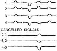
Figure 2-30A. - Fixed target cancellation. 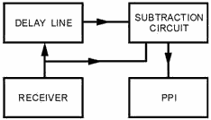
Figure 2-30B. - Fixed target cancellation. In figure 2-31, 30-megahertz signals from the signal mixer are applied to the 30-megahertz amplifier.
The signals are then amplified, limited, and fed to the phase detector. Another 30-megahertz signal, obtained from
the coherent oscillator (coho) mixer, is applied as a lock pulse to the coho. The coho lock pulse is originated by
the transmitted pulse. It is used to synchronize the coho to a fixed phase relationship with the transmitted
frequency at each transmitted pulse. The 30-megahertz, CW reference signal output of the coho is applied, together
with the 30-megahertz echo signal, to the phase detector. 2-43

Figure 2-31. - MTI block diagram. The phase detector produces a video signal. The amplitude of the video signal is determined by the phase
difference between the coho reference signal and the IF echo signals. This phase difference is the same as that
between the actual transmitted pulse and its echo. The resultant video signal may be either positive or negative.
This video output, called coherent video, is applied to the 14-megahertz CW carrier oscillator. The 14-megahertz CW carrier frequency is amplitude modulated by the phase-detected coherent video. The
modulated signal is amplified and applied to two channels. One channel delays the 14-megahertz signal for a
period equal to the time between transmitted pulses. The signal is then amplified and detected. The delay required
(the period between transmitted pulses) is obtained by using a mercury delay line or a fused-quartz delay line,
which operates ultrasonically at 14 megahertz. The signal to the other channel is amplified and detected with
no delay introduced. This channel includes an attenuating network that introduces the same amount of attenuation
as does the delay line in the delayed video channel. The resulting nondelayed video signal is combined in opposite
polarity with the delayed signal. The amplitude difference, if any, at the comparison point between the two video
signals is amplified; because the signal is bipolar, it is made unipolar. The resultant video signal, which
represents only moving targets, is sent to the indicator system for display. An analysis of the MTI system
operation just described shows that signals from fixed targets produce in the phase detector recurring video
signals of the same amplitude and polarity. (Fixed targets have an unchanging phase relationship to their
respective transmitted pulses.) Thus, when one video pulse is 2-44
combined with the preceding pulse of opposite polarity, the video signals cancel and are not passed on
to the indicator system. Signals from moving targets, however, will have a varying phase relationship with
the transmitted pulse. As a result, the signals from successive receiving periods produce signals of different
amplitudes in the phase detector. When such signals are combined, the difference in signal amplitude provides a
video signal that is sent to the indicator system for display. The timing circuits, shown in figure 2-31,
are used to accurately control the transmitter pulse- repetition frequency to ensure that the pulse-repetition
time remains constant from pulse to pulse. This is necessary, of course, for the pulses arriving at the comparison
point to coincide in time and achieve cancellation of fixed targets. As shown in figure 2-31, a feedback
loop is used from the output of the delay channel, through the pickoff amplifier, to the trigger generator and
gating multivibrator circuits. The leading edge of the square wave produced by the detected carrier wave in the
delayed video channel is differentiated at the pickoff amplifier. It is used to activate the trigger generator and
gating multivibrator. The trigger generator sends an amplified trigger pulse to the modulator, causing the radar
set to transmit. The gating multivibrator is also triggered by the negative spike from the differentiated
square wave. This stage applies a 2,000-microsecond negative gate to the 14-megahertz oscillator. The oscillator
operates for 2,400 microseconds and is then cut off. Because the delay line time is 2,500 microseconds, the
14-megahertz oscillations stop before the initial waves reach the end of the delay line. This wave train, when
detected and differentiated, turns the gating multivibrator on, producing another 2,400- microsecond wave train.
The 100 microseconds of the delay line is necessary to ensure that the mechanical waves within the line have time
to damp out before the next pulse-repetition time. In this manner the pulse-repetition time of the radar set is
controlled by the delay of the mercury, or quartz delay line. Because this delay line is also common to the video
pulses going to the comparison point, the delayed and the undelayed video pulses will arrive at exactly the same
time. Q44. What type of target has a fixed phase relationship from one receiving period to the next?
Q45. What signal is used to synchronize the coherent oscillator to a fixed phase relationship with the
transmitted pulse? Q46. What is the phase relationship between the delayed and undelayed video?
Logarithmic Receiver The LOGARITHMIC RECEIVER uses a linear logarithmic amplifier, commonly called a
LIN-LOG Amplifier, instead of a normal IF amplifier. The lin-log amplifier is a nonsaturating amplifier that does
not ordinarily use any special gain-control circuits. The output voltage of the lin-log amplifier is a linear
function of the input voltage for low-amplitude signals. It is a logarithmic function for high-amplitude signals.
In other words, the range of linear amplification does not end at a definite saturation point, as is the case in
normal IF amplifiers. The comparison of the response curves for normal IF and lin-log amplifiers is shown in
figure 2-32. The curves show that a continued increase in the input to the lin-log amplifier causes a continued
increase in the output, but at a reduced rate. Therefore, a large signal does not saturate the lin-log amplifier;
rather, it merely reduces the amplification of a simultaneously applied small signal. a small echo signal can
often be detected by the lin-log receiver when a normal receiver would be saturated. 2-45
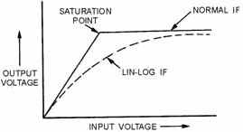
Figure 2-32. - Lin-Log amplifier versus normal IF amplifier. A typical circuit for obtaining a lin-log response is shown in figure 2-33. If detectors 2 and 3 were
not present, the output voltage would be limited by the saturation point of the final IF stage, as it is in a
normal IF section. However, when the final stage of the lin-log is saturated, larger signals cause an increase in
the output of the next to last stage. This increase is detected by detector 2 and summed with the output of
detector 1. This sum produces an increase in the output even though the final stage is saturated. Detector 3
causes the output to continue to increase after the second stage saturates. The overall gain becomes less and less
as each stage saturates, but some degree of amplification is still available. The proper choice of IF stage gains
and saturation points produces an approximately logarithmic response curve. 
Figure 2-33. - Lin-Log receiver block diagram. Figure 2-34, shows the response curves of the three IF stages in the lin-log amplifier shown in figure
2-33. The responses of the individual stages produce a segmented overall response curve for the receiver. 2-46
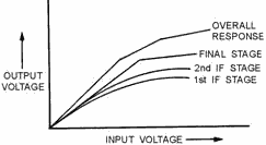
Figure 2-34. - Lin-Log amplifier stage response curves. Monopulse Receiver The most common of the automatic tracking radars is the
MONOPULSE Radar. The monopulse radar obtains the three target position coordinates of range, bearing, and
elevation from a single pulse. The receiver for a monopulse radar must have three separate channels to process
range, bearing, and elevation information. The block diagram of a simplified monopulse receiver is shown in figure
2-35. 
Figure 2-35. - Monopulse receiver block diagram. As in a conventional receiver, each channel of the monopulse receiver converts the return echo to an IF
frequency by mixing the returned signal with a common local oscillator signal. The sum of the energy from all four
return signals is mixed with the local oscillator signal to produce range IF information. Bearing information is
obtained by subtracting the energy from horns B and D from the energy from horns a and C: 2-47
(A + C) - (B + D) and mixing the difference with the local oscillator signal. The result is a bearing IF signal. Elevation
information is obtained in the same way, except the energy from horns C and D is subtracted from the energy from
horns a and B:
(A + B) - (C + D) If the target is on the elevation and bearing axis, the summations will both be zero; therefore, neither the
bearing nor elevation channels will receive an input signal. If either of the bearing or elevation signals is off
the axis, an input to the IF channel is produced. This input is subsequently converted to an IF signal in the
appropriate channel.
The major difference between the monopulse receiver and the conventional receiver is the requirement for a
dc error voltage output from the bearing and elevation channels. The range channel of a monopulse receiver is sent
to a conventional ranging circuit for presentation are on an indicator or for use by a range-tracking circuit.
However, since most monopulse radars are automatic tracking radars, the outputs of the bearing and elevation
channels must be converted to dc error signals for use by automatic bearing and elevation tracking systems. The dc
error voltages are applied to the antenna bearing and elevation positioning servos. These servos reposition the
antenna until the errors are nulled. The phase detectors compare the phase of the bearing and elevation IF
with a reference IF from the range channels. This comparison produces the dc error pulses needed to drive the
antenna servos. The signals from both the bearing and elevation channels are the result of a summation process.
They can be either positive (in-phase) or negative (180-degrees out of phase) when compared to the reference IF
signal. For example, if the output of horns a and C is smaller than the output of horns B and D, a negative or
180-degree-out-of-phase signal is produced by the bearing channel (A + C) - (B + D). If output a + C is greater
than output B + D, a positive or in-phase signal is produced by the bearing channel. The phase of the bearing and
elevation output signals determines the direction in which the antenna moves; the magnitude of the signal
determines the amount of movement. Since two signals must be present at the phase detector to produce an output,
an error signal occurs only when a return echo is not on the antenna beam axis. This technique produces an
error signal when the target moves off the radiated beam axis in either bearing or elevation. The error signal
causes the antenna to move in the proper direction and for the proper duration to cancel the error signal. This
method of automatic tracking is commonly used by weapons-control tracking radar systems.
Q47. When a large signal and a small signal are applied to a lin-log amplifier at the same time, what is
the effect on the small signal? Q48. What happens to the overall gain of a lin-log amplifier as each
stage saturates? Q49. a monopulse receiver has how many separate channels? Q50. If a target is on
the bearing axis of the radiated beam, what is the input to the bearing IF channel? Q51. What
characteristic of the bearing and elevation output signals determines the direction of antenna movement? 2-48
Summary The following paragraphs summarize the important points of this chapter. The Synchronizer
is essential to any radar because it controls and times the operation of the entire system. Radar systems may be
self-synchronized by triggers from the transmitter or externally synchronized from a master oscillator. Most modern systems are synchronized by a MASTER Oscillator, which may be a SINEWAVE Oscillator,
an ASTABLE MULTIVIBRATOR, or a BlockING Oscillator. Each of these oscillators fulfills the basic
requirements of a synchronizer, which must be: • free running • stable in frequency •
frequency variable (in steps) The Transmitter produces the short-duration, high-power, RF
pulses of energy that are radiated into space by the antenna. The Modulator controls the
radar pulse, width and amplitude. KEYED-Oscillator Transmitters produce a high-power
output pulse by keying a high- power oscillator, such as a MAGNETRON. Power-Amplifier Transmitters
amplify a low-level pulse to the desired power level using a series of microwave amplifiers such as TRAVELING-WAVE
TUBES or KLYSTRONS. The DUPLEXER is a device that allows the same antenna to both
transmit and receive. Most duplexers use the impedance characteristics of transmission lines and waveguides in
conjunction with TR and ATR tubes to route the energy to the correct place. One of the most important functions of
the duplexer is isolation of the receiver during transmission. The RECEIVER detects the
very small target return echo and amplifies it to a usable level for display on the indicator. A typical
SUPERHETERODYNE RECEIVER
consists of a low-noise amplifier, a mixer, a local oscillator, an IF amplifier, a detector, and a video
amplifier.
Some special purpose receivers are the MOVING TARGET INDICATOR and MONOPULSE RECEIVERS. Answers to Questions Q1. Through Q51. A1. Controls system operation and timing. A2. Timing and control. A3. Transmitter. A4.
Free-running. 2-49
A5. The master oscillator. A6. Leakage from the duplexer. A7. Sine-wave oscillator,
single-swing blocking oscillator, and master-trigger (astable) multivibrator. A8. It requires additional
shaping circuits.
A9. Blocking oscillators. A10. Keyed oscillator and power-amplifier chain. A11. The
modulator.
A12. Steep leading and trailing edges. A13. Line-pulsed. A14. Capacitor, artificial
transmission line, or pulse-forming network. A15. Pulse width. A16. Thyratron. A17. The
charging impedance.
A18. 600-30,000 megahertz. A19. Mode skipping and mode shifting. A20. The magnetron will
not oscillate. A21. +5 percent. A22. Frequency stability. A23. Local oscillator and coherent
oscillator.
A24. Multicavity klystron. A25. Frequency synthesizer. A26. Oscillations at an undesired
frequency.
A27. Electronic. A28. TR tube. A29. Apply keep-alive voltage. A30.
Quarter-wavelength section. A31. Transmit. A32. Neither fires. A33. 180 degrees out of
phase. 2-50
A34. Noise. A35. Superheterodyne. A36. Thirty or sixty megahertz. A37. Local
oscillator.
A38. Mixer. A39. Cascade. A40. Detector. A41. IAGC. A42. Zero. A43. FTC has no effect on receiver gain. A44. Stationary. A45. Coho lock pulse. A46.
Opposite.
A47. Amplification is reduced. A48. Decreases. A49. Three. A50. Zero. A51.
Phase. 2-51
| - |
Matter, Energy,
and Direct Current |
| - |
Alternating Current and Transformers |
| - |
Circuit Protection, Control, and Measurement |
| - |
Electrical Conductors, Wiring Techniques,
and Schematic Reading |
| - |
Generators and Motors |
| - |
Electronic Emission, Tubes, and Power Supplies |
| - |
Solid-State Devices and Power Supplies |
| - |
Amplifiers |
| - |
Wave-Generation and Wave-Shaping Circuits |
| - |
Wave Propagation, Transmission Lines, and
Antennas |
| - |
Microwave Principles |
| - |
Modulation Principles |
| - |
Introduction to Number Systems and Logic Circuits |
| - |
- Introduction to Microelectronics |
| - |
Principles of Synchros, Servos, and Gyros |
| - |
Introduction to Test Equipment |
| - |
Radio-Frequency Communications Principles |
| - |
Radar Principles |
| - |
The Technician's Handbook, Master Glossary |
| - |
Test Methods and Practices |
| - |
Introduction to Digital Computers |
| - |
Magnetic Recording |
| - |
Introduction to Fiber Optics |
| Note: Navy Electricity and Electronics Training
Series (NEETS) content is U.S. Navy property in the public domain. |
|


