|
|||||||||||||
 |
|||||||||||||
| RF System Cascade Calculator | |||||||||||||
|
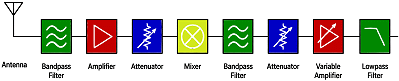
Disclaimer: These calculations are believed to be accurate, but you must validate all results for critical applications. RF Cafe's calculators are entirely unique code - not "borrowed" from somebody else's work. This RF Systems Cascade Calculator handles up to eight stages. IP2, IP3, and P1dB values are all reference to the stage output. All input stage parameters, Gain, Noise Figure, OIP2, OIP3, and OP1dB, are limited to ±200. P[input] has a lower limit of -174 dBm (GTB in 1 Hz bandwidth). AI provided most of the PHP code after many iterations of instructions, but it is amazing what it came up with - and with very few lines of code. AI code is impressively efficient - at least compared to the bloated, sophomoric stuff I turn out. My Espresso Engineering Workbook (free) contains a similar calculator, and my RF Cascade Workbook (nominal cost) contains a much more sophisticated RF system cascade calculator.
See some of my other calculators: Attenuator Calculator, Directional Coupler Calculator, Fresnel Zone Calculator; RF System Cascade Calculator |
|||||||||||||
 |
|||||||||||||
|
|||||||||||||

|
||||||||||||||||||||||||||||||||||||