|
|||||||||||||
 |
|||||||||||||
LP Gas Tank and Supply Line Installation
|
|||||||||||||
|
<Previous Next>
LP Gas Tank and Supply Line Installation - completed project. By Kirt Blattenberger, In mid-June (2026), I detected a rather strong odor of LP gas in the vicinity of an 300-gallon underground storage tank in my daughter's yard. I had detected it a few times before, usually after a strong rain. My guess is that the gas permeated the soil during a dry spell, then was forced out as water saturated the ground. LP gas if heavier than air, so it would tend to prefer residence in the ground if its source was there.
1 | 2 | 3 | 4 | 5 | 6 | 7 | 8 | 9 | 10 | 11 | 12 | 13 | 14 | 15 | 16 | 17 | 18 | 19 | 20 | 21 | 22 | 23 | 24 | 25 | 26 | 27 | 28 | 29 | 30 | 31 | 32 | 33 | 34 | 35 | 36 | 37 The tank, of late 1980s vintage, is buried about 30 feet from the house, which in and of itself is OK per code, but the disturbing part is that my grandson's play yard is right over top of it. Previous attempts to "scare" the adults into relocating the tank had no effect. This time, though, there was no ignoring it. The fuel level indicator was showing a rapid loss of content, and the only thing using the LP gas is a 26 kW Generac whole-house generator that only runs every two weeks for 12-15 minutes to do a self-check and charge the starting battery. Action was needed immediately. It has only been a few months since the underground 240-volt AC feeder line to the farm buildings lost one leg (down to 120 volts). That necessitated a complete redo of the electrical supply system, which included burying a new 150-amp feeder line in PVC conduit to the first building, and replacing a rickety overhead feed to another group of buildings (the property is a small, retired dairy farm). Details of the endeavor can be found at Underground Service Cable and Circuit Breaker Panel Replacement. Now, it was time to switch hats from electrician to gas technician. My experience with electrical work is extensive, but with gas, not so much - especially for such a major undertaking. Fortunately, a huge amount of research, including local codes, industry best practices, and manufacturers' data, provided the necessary information.
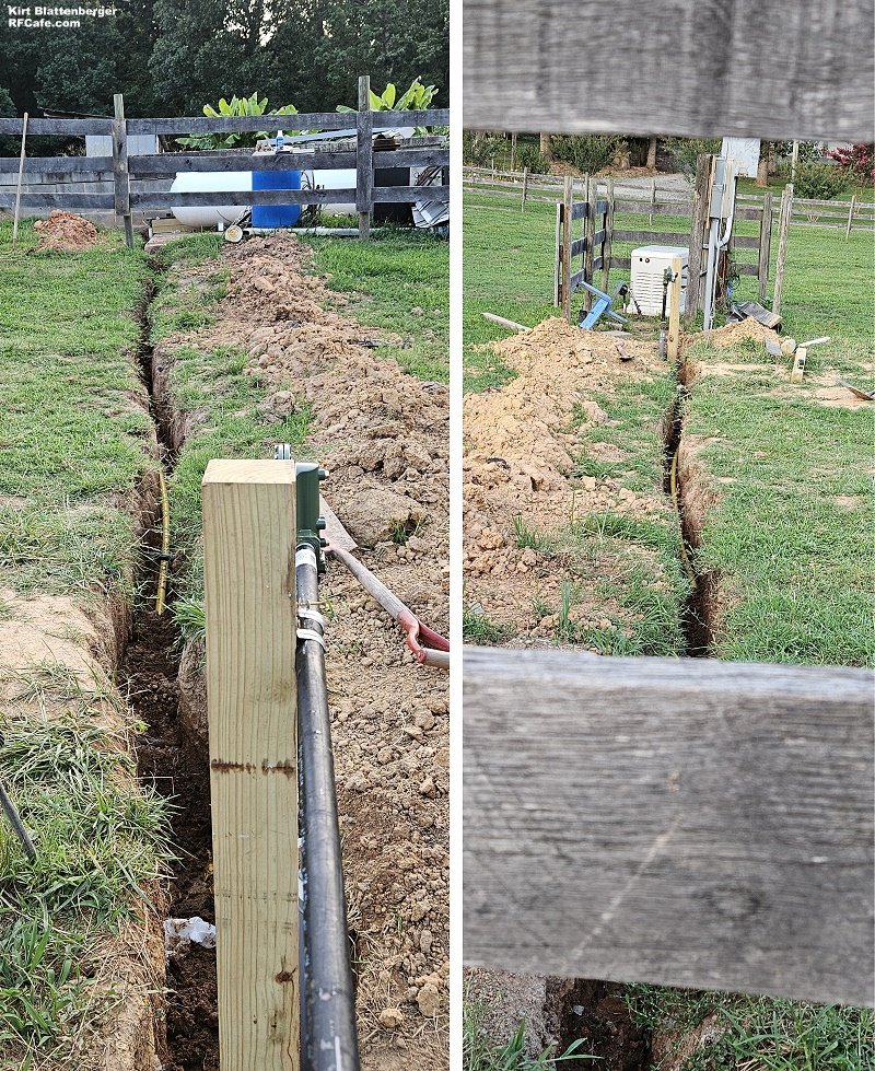
End-to-end LP gas line installation trenches.
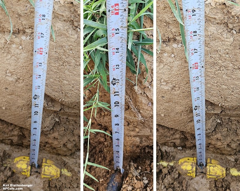
LP gas line burial depth.
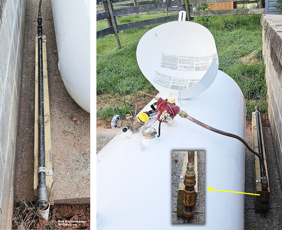
LP gas line run from LP gas tank to launch into ground. "Tee" fitting with plug installed to accommodate possible future need. Note sediment trap. I think maybe the BigBlue leak detector fluid cause the rust to form on the iron pipe fittings.
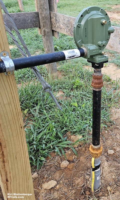
Secondary (low pressure) LP gas regulator.
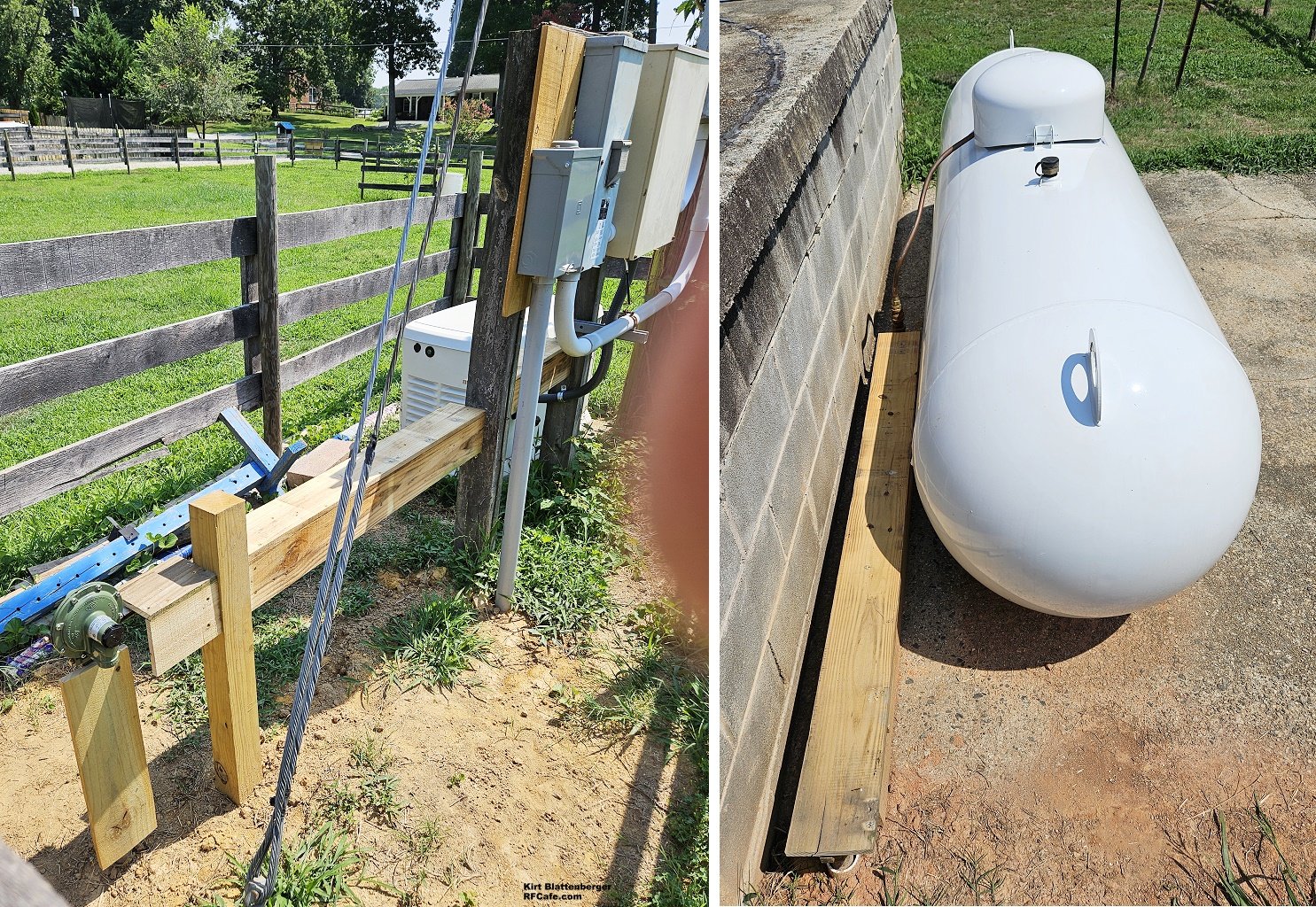
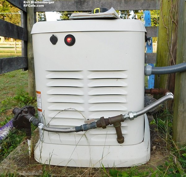
LP gas line connection to 26 kW Generac generator. Note sediment trap.
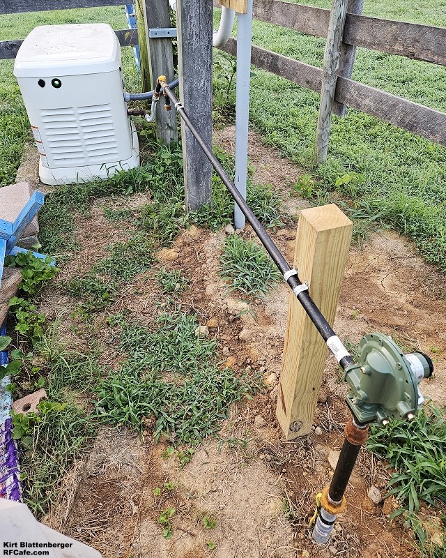
Entire LP gas line path from ground exit to generator.
Original LP gas line connection from underground storage tank. The first course of action was to procure an above-ground LP gas tank. We decided that a 330-gallon job would be sufficient to run the generator for at least a week with low demand. LP gas tanks are outrageously expensive. If you can find a used one - which I did not want - the cost would be around $1,000-$1,500. A spanking new 330-gallon tank cost $2,600. Ouch. There was already a 12'x12' concrete pad located about 50 feet from the generator and about 150' from the house, so we chose that. The generator, as the photos show, is in a fenced-off area in one of the horse pastures, so the tank didn't want to go there. Planning the installation, generating a layout and parts list, and procuring all the pipe, fittings, valves, pressure regulators, test instruments, pipe tape and dope, and research took a little over a week. That included driving 30 miles to get the tank into the back of a Chevy Silverado 2500 pickup truck. A tractor easily lifted it from the truck bed and set it in place. I hand-dug a trench in this nasty, hard red clay ground to a depth that put the top of the 1" diameter yellow gas pipe no less than approximately 16" below grade. Code says 12" minimum. There hadn't been much rain for months, so the ground was like baked adobe. In most of it, I needed to break the surface down a couple of inches, run water in it and let it soak for a while, then dig some more. That process was repeated a few times. For about half the distance, there was thin layer of crushed rock just below the surface from where the farmer had spread it around the concrete pad - part of a much larger structure that once held a huge milk storage tank. If you are not familiar with gas supply installations, two regulators are required. A high pressure regulator at the storage tank output connection drops pressure from 60-160 psi in the tank (depending on temperature) down to 10-12 psi According to industry-wide code, and then a low pressure regulator drops that pressure down to 11-13 WC. WC stands for "water column," which is equivalent to 0.36-0.43 psi†, or 2.49-2.99 kPa. The regulator on your patio gas grill has a combined 2-stage regulator that does the same thing. Code requires that the low pressure regulator not be located less than 5 feet from any source of ignition. That is because it has an over-pressure relief valve that could potentially release gas into the air. That meant at lest 5 feet from the generator, but there are also 240-volt electrical panels in the area for the automatic switchover gear and a 200-A main circuit breaker for the entire property, so the regulator ended up about 7 feet from the generator. Also, the manufacturer wants the regulator at least 2 feet from the ground to prevent dirt and grass from being splashed up into the relief outlet on the bottom of the regulator. Most of the installation was completed in a day. I did not start until all the components were on hand. 1" black pipe and yellow polyethylene pipe was used from the LP gas tank connection over to the second-stage regulator, then 3/4" black pipe was used from there to the generator. An insulated tracer wire was laid in the trench with the pipe. The most expensive single part other than the high-pressure(1st stage) and low-pressure (2nd-stage) regulators (~$120 each) was the 1" plastic-to-iron-pipe sweep bend transitioning from the underground polyethylene pipe to above-ground iron pipe - about $75 each (2 required). Couplers for the plastic pipe are $30 each (qty. 2). Black iron pipe cost about $5-6 per foot. Ells, couplers, and adapters were around $5-10 apiece, and the 1" unions (qty. 2) were a whopping $30 each. I kept the number of bends to a minimum, but in all ended up with around 6*90° = 540° worth of bends, only 3 of which were were hard 90° bends, the other were sweeps. Total cost of parts was around $600. Special equipment was about $200 for digital manometer (aka pressure gauge), pipe flaring tool (for copper pipe between LP gas tank 1st stage pressure regulator and black iron pipe fittings), and leak detection fluid. Yellow pipe dope was used on all the joints, and they were tightened to what I thought, based on research, was ample torque, without being too aggressive. Turns out, I should have been a lot more aggressive. After charging the line with air to 15 psi, leaks appeared all over the place. Most were cured with more torqueing of the joints. Some required disassembly, wrapping with yellow gas tape, doping, and reassembling with plenty of torque. Finally, pressure held for many hours. Then after sitting exposed to the hot sun all day and then cooling, tiny leaks began appearing. I started out using some brush-on leak detector fluid, but even though it showed no signs of leaks anywhere in the path, the system would lose 2-4 psi overnight. I discovered the mechanical pressure gauge (new, 15 psi max) was leaking a smidge internally so it was isolated from the system by a small valve. Still, a small leak persisted. Out of desperation, I paid $25 for a spray bottle of BigBlue Microleak Detector. It has a lower viscosity and much higher surface tension, which allows bubbles to grow over hours without popping. With that, I was able to find the small leaks and fixed them with a combination of yellow gas tape and yellow gas dope, and a lot of torque. Finally, after four days of chasing down microleaks, the pressure held for two days. Inspection only requires the system to be charged with 150% of the normal working pressure (1.5 x 10 psi = 15 psi) and for it to not indicate any loss after 15 minutes. This experience has me believing that there are a huge number of gas piping systems out there that passed inspection, but have some degree of leakage. I can't be the only schmo who has had to deal with so many microleaks. Yesterday, about three weeks after beginning the process, was the moment of truth. After having 100 gallons delivered into the 330-gallon LP gas tank, I purged the air from the line all the way to the generator input (out through the pressure test port on the generator itself), and fired her up. After about 45 seconds of cranking (in two time segments), the beast took off - running, that is, not into space as it blew up ;-) In order to help reduce exposure to severe heating and cooling cycles, I installed a shade over most of the exposed pipe. Mission completed. Total project parts cost was around $3,500. Now, I'll monitor the joints with BigBlue to make sure no leaks creep in. One more note here on the generator installation. A 12-kW, 240-volt Guardian generator was in place when my daughter and son-in-law bought the retired dairy farm a few years ago. It was not really sufficient to service the house during severe cold weather when the auxiliary resistance heat coils might be needed to supplement the heat pump. It was very unreliable and failed to start when needed during storms with heavy rain - just when it was needed most. We went to 26 kW based on my demand calculations and a plan to limit energy usage whilst on generator power. The original gas line system had a 120' length of 1/2" copper pipe buried in the ground between the underground storage tank and the generator (in some places less that 6" below the surface!). The Generac manual dictates 1" pipe for runs between 40' and 160', so that old line would never have been able to supply enough gas under full load, or even half load. Even though around $800 worth of LP gas leaked from the old tank, I consider the entire event a blessing in disguise from safety, reliability, and performance perspectives. I'm sure glad that's all behind me! † Derivation of WC in equivalent PSI: Pressure is that weight divided by 1 in², so: psi = inches WC / 27.68 or psi=inches WC * 0.03613 For 11" WC:
The exact conversion factor depends slightly on water temperature (density changes), but 27.68" WC per psi (or 0.03613 psi per in WC) is standard for near‑room‑temperature water. Disclaimer: The author is not a licensed gas contractor, and this account describes a personal project completed and believed to be in compliance with local codes at the time of installation. Gas piping work involves serious risks of fire and explosion. This article is for informational and educational purposes only and does not constitute professional advice. Always consult a qualified, licensed professional before undertaking any gas-related work. Follow all applicable local codes and manufacturer instructions. |
|||||||||||||
 |
|||||||||||||
|
|||||||||||||
 "
"


|
||||||||||||||||||||||||||||||||||||