|
|||||||||||||
 |
|||||||||||||
Ring Oscillators for U.H.F. Transmission
|
|||||||||||||
Achieving clean oscillations above about 300 MHz (1 meter wavelength) from standard glass and metal vacuum tubes is difficult due to interelectrode capacitances and self-inductance of internal wires and grid plates. Generating high power for applications like radar and long distance communications was made possible with the invention of klystron, magnetron, and ring oscillator tubes during World War II years. The UHF radio band spans from 300 MHz to 3 GHz, and it is the upper end of the band where the wavelength is short enough (3.93 inches | 10.0 cm for 3 GHz) to provide adequate spatial resolution for radar. The ring oscillator, unlike a magnetron with a solid chunk of metal with machined cavities and coupling windows, uses separate high power tubes with tuned coaxial lines between sections to isolate mutual inductance and capacitance loading effects that would otherwise limit the upper frequency of operation. Ring Oscillators for U.H.F. Transmission
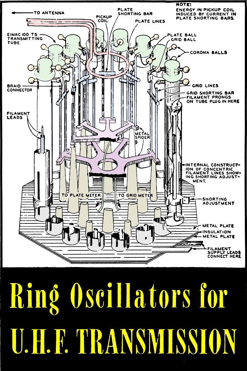
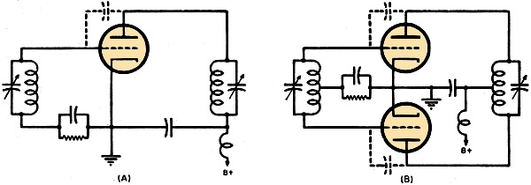
Cut-away drawing of typical ring oscillator used in Army Signal Corps radar equipment. SCR-268, showing circular arrangement of tube and circuit components in one method of construction. By Tom Gootée A wartime development that contributes to the efficient operation of tubes at high frequencies, thus permitting high power outputs to be more readily accomplished. Generation of u.h.f. oscillations above 300 megacycles is an impossible task for conventional types of vacuum tubes, because of the effects of inter electrode capacitance and electron transit time, and the effects of distributed inductance and capacitance in tube leads. Special types of high-frequency triodes - developed within recent years - have overcome some of these limitations to a degree, .and many of the tubes can function as negative-grid oscillators at frequencies well beyond 1000 megacycles. But these special triodes cannot carry large amounts of current, and therefore their output power is relatively low for most u.h.f. requirements. And the old bugaboo: inter-electrode capacitance, though of lower magnitude, is still present. And it is still objectionable, since it limits the highest operating frequency of a vacuum tube. The only solution to the problem of generating very high power with u.h.f. triodes is by arranging an even number of them in a wholly new type of u.h.f. oscillating circuit, known as a ring oscillator. Any type of special u.h.f. triodes may be used in this arrangement, their combination providing not only a greater power output but also an extension of the upper limit of frequency operation in the u.h.f. band. Thus, an even number of four or more triodes will oscillate at higher operating frequencies and with greater power output than would be possible with one or two vacuum tubes of the same type. Basically, the circuit is a special type of tuned-plate, tuned-grid oscillator. The development of the ring oscillator is closely allied with the fundamental feedback circuit. Basic Circuits The circuit for the basic tuned-plate tuned-grid oscillator (Fig. 1A) uses a single vacuum tube and a resonant coil-and-condenser tank circuit in both grid and plate circuits. Action of the oscillator is predicated on the feedback of energy from plate to grid circuits by means of the plate-to-grid interelectrode capacitance within the tube itself. In operation, alternating voltage fed back to the grid of the triode is 180 degrees out-of-phase with the alternating voltage in the plate circuit, and the grid voltage is of sufficient amplitude to develop the output power required to maintain this voltage. Frequency of oscillations is slightly lower than the resonant frequency of the plate and grid tank circuits. The two circuits need not be in exact resonance with each other, since frequency of oscillations is determined primarily by constants of the plate circuit. The grid tank circuit controls the degree of excitation. At the operating frequency, both tank circuits offer inductive reactance to the flow of current. But to sustain oscillations, reactance of the plate-to-grid interelectrode capacitance must be greater than the inductive reactance of the grid tank circuit. Grid current in a tuned-plate, tuned-grid oscillator effectively leads the plate voltage by more than 90 degrees, so that voltage fed back to the grid of the tube is exactly in phase with the plate current. This satisfies the oscillator requirement of a negative resistance of magnitude sufficient to compensate for all losses in the circuit. Fixed bias (such as a battery) is seldom used in feedback oscillators. Invariably used is resistance bias, so the circuit will be self-starting and stable operation will be ensured. To obtain an output power greater than that for a single triode, two or more tubes may be connected in parallel. However, this serves no practical advantage, because all tube interelectrode capacitances are also paralleled. This increases the minimum circuit capacitance, decreases the tuning range, and causes the development of parasitic oscillations. For these reasons, parallel-connected oscillators are not useful for generating ultra-high frequencies. To obtain increased output and also greater frequency stability, a double-ended arrangement of the tuned-plate, tuned-grid circuit may be used. In this arrangement (Fig. 1B), two triodes of the same type are connected in push-pull. Operation of this circuit also depends upon the interelectrode capacitance of each tube. Oscillations are sustained when a sufficient portion of the voltage in the plate circuit is fed back to the grid circuit. The two triodes are balanced against ground, and each tube handles an alternation opposite in original polarity to that handled by the other tube - so that both alternations are utilized. In this way, even-order harmonics are effectively cancelled out in the plate circuit. Oscillations normally tend to increase in amplitude until the energy lost in the grid and plate tanks is exactly equal to the energy supplied the tank circuits by the two triodes. Maximum amplitude of oscillations is called the saturation amplitude, since the two tubes are driven into the plate-current saturation region of their characteristic curves. Since interelectrode capacitances of the two tubes are effectively in series, theoretically their combined value would be one-half that for a single triode - considerably extending the highest frequency at which the oscillator may be operated. However, at ultra-high frequencies, the distributed inductance of the tube leads which are also in series tends to overcome the advantage of decreasing input capacitance.
Fig. 1 - Basic (A) and push-pull (B) tuned-grid, tuned-plate oscillators. Resonant Lines Effects of distributed inductance and capacitance in circuit components directly associated with the oscillator can be minimized by using extremely short leads and resonant lines. Use of resonant or Lecher lines also contributes to extreme frequency stability and increased power output of the tuned-plate, tuned-grid oscillator. This takes place because both output power and frequency stability are functions of the "Q" of the oscillator's resonant tank circuits. "Q" is a factor-of-merit, determining the sharpness of resonance of a tuned circuit. Considering the basic push-pull circuit (Fig. 1B), to obtain a high "Q" required for efficient u.h.f. operation, the r.f. resistance must be low. This would require use of a very large conductor, since u.h.f. current flows only on the outer surface. Also essential is a large inductance, compared to the capacitance of the tank circuit. But this is practically impossible, since interelectrode capacitances of the tube are limiting factors. Therefore the "Q" of a coil-and-condenser tank circuit, even at best, leaves much to be desired for ultra-high frequency operation. Quarter-wave resonant lines have very high values of "Q," and therefore are ideal as tuned tank circuits for ultra-high frequency operation. High values of "Q" - between 5000 and 10,000 - are made possible by the construction of the resonant or Lecher lines, which minimize skin effect. As the operating frequency is increased, the length of the resonant line decreases faster than the skin effect increases. Thus, the value of "Q" increases with frequency of operation. The basic push-pull circuit (See Fig. 1B) has been redrawn in Fig. 2, showing the substitution of tuned resonant lines for the previous coil-and-condenser tank circuits. The circuit operates in much the same manner as the basic push-pull tuned-plate, tuned-grid oscillator. Differences are mainly physical or mechanical ones. Grid and plate terminals of the two triodes are generally connected directly across the open end of their respective resonant lines. Since the high-"Q" circuit is also a high impedance device, direct connections permit the oscillator tubes to work into maximum impedance, thus delivering optimum power output. The only disadvantage of resonant lines is the shunt-loading effect of the triodes, which loads down the line and diminishes slightly the value of "Q."
Fig. 2 - Ultra-high frequency push-pull tuned-grid, tuned-plate oscillator. Resultant operation is something of a compromise; high power output with relatively moderate stability. Tuning of resonant lines is accomplished by "shorting bars," which resonate the lines at a given operating frequency. The u.h.f. energy can be coupled out of the push-pull resonant-line oscilla-tor (Fig. 2) by inductive, capacitive, or direct connection. Inductive coupling to the grid circuit-by means of a one-turn loop - is critical. because coupling may seriously reduce the "Q" of the grid resonant circuit to such an extent that frequency control is influenced. Inductive coupling to the plate circuit results in an extremely high potential between the plate line and the one-turn coupling loop. This potential is the sum of the d.c. and r.f. voltages. For this reason, precautions must be taken to prevent possible arcing. The degree of inductive coupling is often so limited that in some cases optimum coupling (maximum transfer of energy) cannot be obtained. Capacitive coupling is seldom used unless in conjunction with inductive coupling. It is possible to couple into a parallel line by tapping directly to one or both resonant lines, however, this should be done only to those lines carrying no d.c. voltage-such as the cathode or filament Lecher lines. Use of d.c. blocking condensers is discouraged. These are general considerations of the simple push-pull resonant-line oscillator (Fig. 2). The circuit has good stability of frequency. Although it supplies a power output somewhat higher than any of the oscillators previously described, it is desirable in many u.h.f. applications to transmit signals of much higher power - while retaining good frequency stability. The output power of the push-pull resonant-line oscillator (Fig. 2) is limited by the plate dissipation of the triodes and by the magnitude of plate current that can flow in the plate circuit.
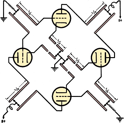
Fig. 3 - Schematic diagram of u.h.f. tuned-grid, tuned-plate ring oscillator. Increasing the temperature of the filaments may permit greater emission, but this greatly shortens the life of the u.h.f. triodes, and is therefore undesirable. A combination of four tubes arranged in push-pull parallel would increase the current-carrying capacity of the oscillator. However, the combined interelectrode capacitance would also be increased by such an arrangement, and parasitic oscillations would be prevalent. So, despite a higher output power, the upper limit of frequency operation would be limited and general efficiency of the circuit would be only fair. For this reason, use of the parallel push-pull oscillator for ultra-high frequency work should be avoided. Solution of the problem of generating high power of stabilized frequency - with u.h.f. triodes - is a development of the simple push-pull resonant-line oscillator. This new circuit is known as a ring oscillator, and consists of any even number of four or more of the same triode types arranged concentrically and tuned with resonant lines. Basic Ring Oscillator The simplest type of ring oscillator consists of four tubes, arranged as shown in Fig. 3. Fundamentally it functions much as any tuned-plate, tuned-grid oscillator - using resonant or Lecher lines. Leads between plates and grids of adjoining tubes connect to quarter-wave resonant lines. A common transmission-line tank serves each pair of grids and each pair of plates. Standing waves of voltage established on sections of the tuned Lecher lines cause the instantaneous voltage on one plate to be 180 degrees out-of-phase with the connecting plate. This voltage relationship plus some inductive coupling inherent between plate and grid circuits plus feedback of alternating voltage through the interelectrode capacitance of each tube combine to produce the necessary conditions for sustained oscillations. Quarter-wave grid and plate lines are tuned to resonance by adjusting the position of the shorting bars. At resonance these shorting bars will be at zero r.f. potential. Half-wave Lecher or coaxial lines are used in the cathode or filament circuit. When tuned to resonance, there will be zero r.f. potential both at the filament and at the shorting bar of each line. In practice, electrical length of the resonant lines varies considerably from the physical length - because of capacitance effects between the various leads and r.f. ground potential, and between the tube elements and ground. This additional capacitive reactance in the circuit results in resonant lines of physical length considerably shorter than the effective electrical length. Operating frequency of the ring oscillator is varied by adjusting the length of the resonant lines of all three tube circuits; grid, plate, and filament or cathode. The plate and grid resonant lines have the greatest effect on the oscillator frequency. The u.h.f. energy can best be coupled out of the 4-tube ring oscillator by a single-turn coil placed between, in the same plane, and in close proximity to the two shorting bars of the plate circuit. Since polarity of the plate resonant lines is in the same direction, current flows in the same direction in each line, and since the resonant lines are a quarter-wave in length and shorted at one end, current will be maximum at the two shorting bars and flowing in the same relative direction. This permits easy coupling by induction. The one-turn coil functions much as the secondary of an air-core transformer, feeding energy directly to the u.h.f. antenna by any kind of low-loss transmission line. Frequency stability of this type of oscillator is good ,and is generally independent of the type of u.h.f. triodes employed in the ring circuit. The arrangement of four tubes provides a power output double that for two triodes (of the same type) arranged in a simple push-pull resonant-line circuit. Since the tubes are effectively in series, the effect of interelectrode capacitance is diminished - permitting operation of the ring oscillator at a higher ultra high frequency than would be possible with only one or two triodes of the same type. Lastly, this circular arrangement also permits, when desired, the use of u.h.f. triodes which are physically large. For the foregoing reasons of stability, greater output power, higher operating frequency, and use of larger vacuum tubes - it is evident that these important advantages can be increased in magnitude by the addition of more and more pairs of triodes to the basic 4-tube ring oscillator. Large Ring Oscillators
Fig. 4 - Wiring diagram of 24 tube u.h.f. ring oscillator. Any even number of u.h.f. triodes of the same type may be connected in this series-circular arrangement, known as a ring oscillator. All of the previous circuit conditions for sustaining oscillations will apply to such multi-tube oscillators. Leads between plates and grids of adjacent tubes connect to quarter-wave resonant lines, each of which is tuned to resonance by a shorting bar. Oscillations take place because of unbalance due to standing waves on the Lecher lines, inherent inductive effects of the circular system, and feedback through the interelectrode capacitance of all tubes. Use of a large number of pairs of triodes does not alter the fundamental circuit operation. Output power of a ring oscillator increases almost linearly with the addition of each pair of tubes; a transmitter with 16 tubes having an output power of approximately 8 times that of a pair of the same type of triodes in a push-pull resonant-line circuit. Maximum high-frequency limit of operation in the u.h.f. band is extended by the addition of each pair of triodes in a ring oscillator. This extension is somewhat logarithmic, but varies in degree according to the type and frequency characteristics of the u.h.f. triodes used in the circular circuit. A typical ring oscillator, consisting of 24 triodes of the same type, is shown in Fig. 4. Quarter-wave sections of resonant lines are used to tune the plate and grid circuits of every tube. Grid tank circuits are connected together by a grid ring - which is biased to r.f. ground. All plate tank circuits are also connected together by a plate ring. Plate voltage is applied through this output ring to all of the u.h.f. triodes. Cathodes or filaments of the oscillating tubes should be operated at r.f. ground potential. At ultra-high frequencies of operation, bypass condensers would not effectively ground the filaments because of high reactance in the filament leads. For this reason, a half-wave section of transmission line - either resonant line, or coaxial cable - is connected to each filament. The far end is shorted to ground, and transformer action of the half-wave line make this r.f. ground appear at the filament of the triode. Since the plate ring is circular in nature, output power is coupled from it by means of a single-loop induction coil placed in the same plane as the plate ring. The method of coupling and physical arrangement of components can be better understood by reference to Fig. 5, showing a portion of the construction of a typical ring oscillator. Physical arrangement of the oscillator places all of the triodes in a circle, equidistant from one another. Plate tank circuits of each pair of triodes are constructed on the inside of the tube circle. If possible, the grid tank circuits should also be on the inside of the circle. The half-wave Lecher or coaxial lines used to tune the cathodes or filaments are generally enclosed in metal cylinders, and each triode is mounted directly atop its respective resonant line.
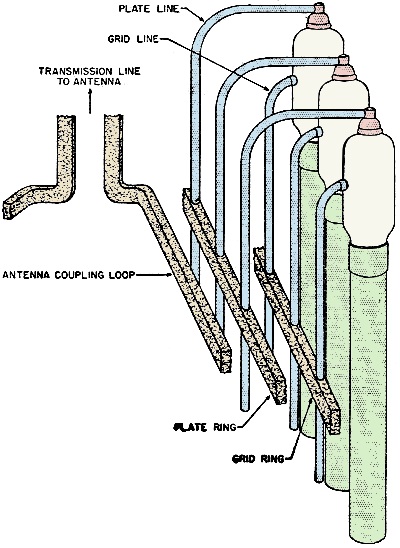
Fig. 5 - Method of coupling employed in ring oscillator. In the interest of space economy, grid and plate tank circuits are also mounted vertically. This arrangement places all of the shorting bars on approximately the same horizontal planes in somewhat of a circle, with the shorting bars of the plate circuits on a different plane and separated from the grid-circuit shorting bars. This separation should be more than one-half wavelength to prevent coupling between the two circuits. In all the plate tank circuits current is maximum in the shorting bars, and flows in the same relative direction. Thus, the bars can be physically and electrically connected together. One arrangement (Fig. 5) connects all of the shorting bars together to form a continuous, circular metal ring. This plate ring shorts every plate tank circuit of the oscillator, and provides a single loop of current. Individual tank circuits can be tuned, as before, by adjusting the position of this plate ring or circular shorting bar. A single-turn loop or coil placed in the same plane and within the circular plate ring will receive u.h.f. energy oscillations by inductive coupling. Coupling to the pickup loop is due to magnetic fields produced by currents in the plate ring. In a somewhat similar manner, individual shorting bars on each of the grid tank circuits may be replaced by a single, continuous, circular metal ring (Fig. 5). The physical arrangement of a multi-tube ring oscillator is considerably simpler than the schematic circuit (Fig. 4) would indicate. Despite its simplicity of construction, however, spacing and arrangement of all components of the oscillator are extremely critical of design. The u.h.f. oscillator has only one disadvantage; it requires a large number of tuning adjustments. Grid rings, plate rings, and shorting bars in the filament circuits all require deft tuning at the resonant frequency of the transmitter. If adjustments are not made properly, considerable inefficiency will result. However, this single disadvantage is offset by the symmetry of physical construction. Equispaced circuit elements and circular arrangement permit ganging of many tuning controls. For most types of the newer u.h.f. triodes, critical circuit adjustments are not necessary to sustain oscillations.
Posted April 13, 2023 |
|||||||||||||
 |
|||||||||||||
|
|||||||||||||
")


|
||||||||||||||||||||||||||||||||||||


