|
|||||||||||||
 |
|||||||||||||
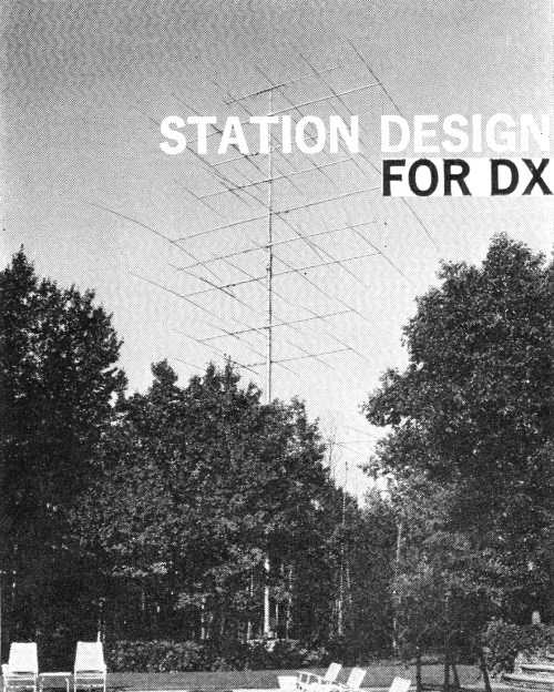
Station Design for DX - Part I |
|||||||||||||
In 1966, Paul Rockwell wrote a 4-part series for the ARRL's QST magazine on station design for long distance communications (DX) that covered antenna selection and siting (Part I), economics and construction (Part II), Station Configuration and Receiver Topics (Part III), and Propagation Quirks and Operating Tips (Part IV). This first part goes into some of the gory detail of surrounding terrain considerations and necessary antenna launch angles, complete with equations. Most of the work is based on multi-element horizontal Yagi antennas. The term "forezone," of which a formal definition is not locatable in a Google search (no reference to it at all), is used throughout the series, and refers to the radiation area in the forward direction. Part I - Antenna Topics and Siting
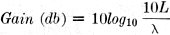
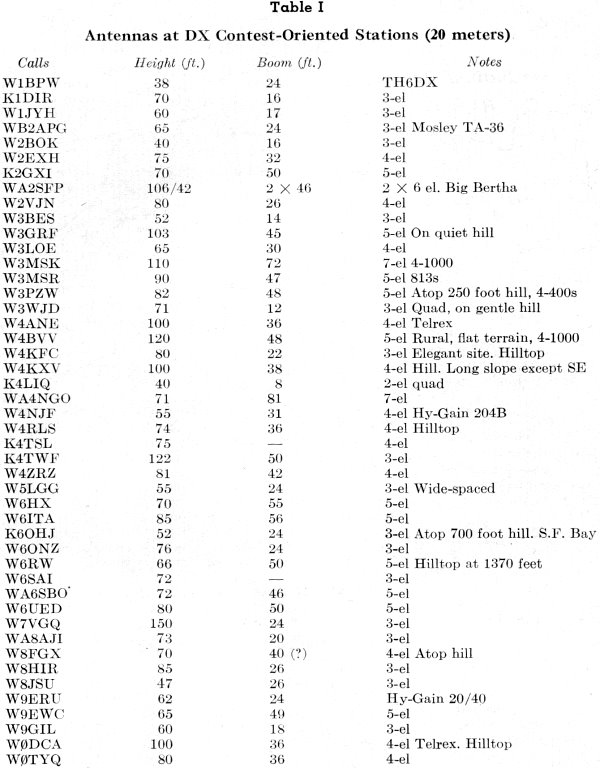
Antenna at K2HLB. By Paul D. Rockwell, * W3AFM Most of what has been written on the subject of optimum station design for DX has been on one aspect at a time. This article assembles various aspects, in the system-approach sense, and is specifically addressed to optimum design for c.w. DX. However, most of the ideas apply also to 'phone operation. Antennas and propagation will be discussed in respects believed to be not generally appreciated. Most of the topics are already familiar to top DXers, but one or more should be useful or interesting to nearly any serious DX operator. The writer expresses his appreciation for many helpful comments and suggestions in voluminous correspondence with top DXers. It was heart-warming to receive so much cheerful encouragement, advice and many contributions. Only one sharp criticism was received: that DX is 90% operator, 10% equipment. Maybe so - but look at Table 1. The successful DX-contest performers who bring up this point usually have several of the following: (a) a full gallon; (b) a tower over 65-feet high; (c) a boom over 30-feet long; (d) a quiet location; (e) a hilltop site. Antenna Topics Firstly, horizontal is by far the preferable polarization. The problem with vertical polarization is primarily with ground losses. Broadcast stations customarily use 120 buried radials to overcome these losses. Such an installation is impractical for amateurs. Radiation efficiency is probably les than 20% for an installation employing say, four radials. G.H. Brown, in PIRE, June, 1937 says that for quarter-wave antennas with 0.4λ radials, efficiencies are: 2 radials.......12.4% 15 radials.....46.2% 60 radials.....64.0% 113 radials...88.0% Furthermore, the vertical radiation pattern is characterized in practical locations by a null at the low angles. The low-angle radiation of a ground-mounted vertical quarter-wave, often shown for perfect earth as being good right down to 0° elevation, actually has a null there. 1,2. Vertically polarized antennas are more susceptible to QRNN (man-made electrical noise) than horizontally polarized. With horizontal polarization, the antenna is balanced with respect to ground, and ground losses are customarily only a few percent. Under certain circumstances, a vertical ground-plane can be advantageous, i.e. (a) for a saltwater reflection-zone, (b) for its set-up convenience on DXpeditions,3 or (c) for constructional and economic advantages on bands lower in frequency than 14 Mc.4 Even in such cases, the vertical loses important advantages of (1) gain, receive and transmit, and (2) receiving effective S/N, including rejection of QRM from undesired directions. Another topic which deserves mention is the question of gain quotations on Yagi antennas. Manufacturers have stated these gains in ways which may be confusing. One manufacturer, for example, chooses to relate the gain of a horizontally-polarized antenna-array at optimum height above ground, to a half-wave dipole in free space. In this way he gives himself 6 db of ground-reflection gain. His quotation should be correspondingly discounted. The practical basis of comparison is to a half-wave dipole, same height and foreground. Almost all manufacturers, when they do not state that the gain is related to a half-wave dipole, are relating their gains to an isotropic radiator. This raises the gain by 2.2 db as compared to gain over a half-wave dipole. If the manufacturer has assumed that the reference isotropic radiator is in free space, whereas his array is at optimum height above a perfectly reflecting ground, then his quotation should be discounted by 8.2 db. The most helpful relation in evaluating gain in a Yagi antenna is the formula:
where L is length of the boom in the same units as the operating wavelength, λ. Here the gain is that of the Yagi over a half-wave dipole, broadside, at the same height and foreground, expressed as a factor.5,6. In db,
This rule is good for optimized designs with element spacings up to approximately 0.2λ maximum. It says some designs are carrying more elements than they need, and may be delivering less-than-optimum performance on that account.
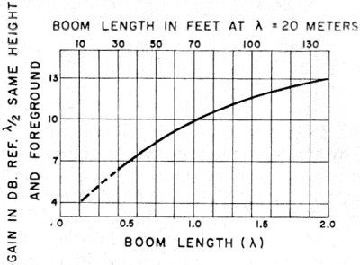
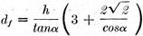
Fig. 1 - Boom Length (λ) vs. Gain (dB) The rule becomes less accurate as the boom length goes below a half wavelength. Fig. 1 is a useful guide. It is taken, and somewhat shaded, from another reference.6 For quads, use Fig. 1 plus 2 db, but only at the quad's optimum-design boom-length. The quad may be considered, for estimating gain patterns, as two vertically-stacked Yagis, The vertical spacing, however, is less than optimum: so 2 db. is a better approximation than the 3 db which would apply in principle for phased arrays. Quad power-gain does not increase linearly with boom length, as is substantially the case with Yagis. Also, quads are more susceptible to side lobes of polarization orthogonal to that of the antenna's nominal polarization. Since h.f. signals arrive with random polarization, this means side responses may be expected to be, relative to Yagis, a problem.7 Measurements of antenna gain are tricky. Usual complications are (a) ground reflections, (b) impedance matching, (c) near-field effects, (d) reflections and absorptions from nearby objects, (e) calibration of measuring detector and attenuators, and (f) polarization effects. When scaling is attempted, further complications are incurred. The subject is treated professionally.8 The same material is published as IEEE Standards No. 149 (Revision of 48 IRE 2S2). January, 1965, and is available from IEEE Headquarters, 345 East 47 Street, New York, N. Y. 10017. W3AFM has worked 310 countries on 20 c.w. only, in the period 1962-1965, from a topographical depression beside a 4-lane highway in the middle of greater Washington, D.C. Looking levelly from. the peak of his roof, he sees neighbors' basement windows on all sides. This is not a construction article. Rather, this series will present some new and stimulating ideas on subjects such as antennas, station apparatus configuration, most useful apportionment of dollar expenditures on various station components; etc. From the foregoing, one might infer that Yagis and quads are all a ham should use. Because they can be rotated, this is not far from correct for 10 through 40 meters, where most DX is worked. Log-periodics are unattractive for hamming because of their low gain, high cost, and structural complications. For really high gain, up to, say 16 db., a rhombic can be a good dollar's worth, real-estate considerations permitting. Rhombics call be nested - that is, several can be stacked, with azimuths in various directions, on the same tract. Inter-couplings are less than commonly supposed.9 Sloping Vs are of course inferior performers.10 Siting The matter of good siting has been appreciated by amateurs for many years. Recent work11 has made the criteria more clear. For the long hauls, the higher the antenna, the better. Try for a radiation angle ("take-off" angle) main lobe at 1° elevation. It is especially effective to locate an antenna of modest height on a cone-shaped hill on which the ground slopes downward in all directions for a thousand feet or so at an angle of, say, 20°. If you have such a fortunate fore zone, 50 feet is a good height for your 20-meter antenna. The formula for angle of maximum radiation (horizontal antennas, flat terrain) is
where h is height (in same units as for wavelength, λ) of the antenna
relative to the ground-reflection zone in the foreground. Required height for a
given take-off angle is The ground-reflection (Fresnel) zone extends as an approximately elliptical area
on the antenna forezone. The geometric ground-reflection point in this zone is at
a distance For 1° take-off angle, flat terrain, at 20 meters, this is about ten miles. The near-end distance of the ground-reflection elliptical area13 is given by
and the far edge by
or about 1.7 and 58 miles, respectively, for 1° take-off.
Fig.2 - Terrain Profiles -- Top: Asia, Center: New Zealand, Bottom: Profile Toward Australia (W.) from W6AM. (The ray tangent is at 51 Miles. Effective height: 1290 feet.)
Table I - Antennas at DX Contest-Oriented Stations (20 meters). Ground reflections have been the subject of published material complete with diagrams.14 A consideration for sloping sites, in addition to the marked reduction of optimum antenna height as mentioned above, is the reduction in size of the ground-reflection area. For a 20° sloping forezone, the reflection area is about the size required for 20° take-off angle on flat terrain, or a maximum far edge of about 1/6 mile. Incidentally, ground losses at h.f. for the grazing angles of interest, say 10° take-off angle, are almost never serious for horizontal polarization and are of the order of a few percent. Ideas of h.f.-site impairment by magnetic masses, etc., under the ground surface are superstitions. Some conspicuous examples of well-sited stations are W3CRA, W4KFC, and W6AM. These stations have (in some directions) radio horizons at distances of 20-50 miles. Radio profiles are presented in Figure 2. Vertical angles are not significant on charts like these. The advantage of a good site and/or a high antenna can be of the order of 10-20 db11 compared with modest suburban-neighborhood installations. It leads to situations where the" mortals down below" can't even hear traces of the other end of comfortably solid DX QSOs being conducted from the best sites. Incidentally, in progressive antenna changes at W3AFM, increments of only 2 db. in antenna gain have opened up, in each case, a new layer of workable central-Asian DX. Examples of high antennas with long-boom Yagis, terrain essentially flat, are W5VA, W3MSK and W3PZW. They, too, conduct what seem to be one-sided DX QSOs. AA quiet location can make a telling difference. W2FZY, who seems to hear everything with a modest antenna, attributes his success largely to quietness of site. Some of the new appliances, notably mixers and bed heater-pads, can ruin DX reception in ordinary urban areas. Where there are only one or two such nuisances, they can be tracked down by auto and portable transistor radios. Their direction can be determined, within about 30°, by beam swinging. Once located, the problem can be corrected by (a) buying a new appliance and trading it for the offending one (b) offering an LC filter (such as Lafayette 99R4005), (c) both the above. W3AFM's worst offenders have been found within 400 feet. Lesser offenders have been located and corrected at distances up to 800 feet. Trees and foliage are less of a problem in h.f. communications than generally imagined. The attenuation varies from a small fraction of a db. for horizontal polarization to 3 db. for vertical polarization. The values apply to 30 Mc through moderately-thick trees as encountered in temperate zones. Attenuation through a brick wall is 2 to 5 db at 30 Mc.15,16 For plotting profiles of your site, excellent contour maps, 7 1/2' X 7 1/2', (i.e. 7 1/2 minutes of latitude by 7 1/2 minutes of longitude) may be had for almost any part of the U. S. A. at 30¢ each. Detail is such that individual houses may often be identified. For explicit ordering information contact: Map Information Service, Geological Survey, Washington, D. C. 20242. (Part II of this series will appear in an early issue.) Footnotes 1 Jordan, "Electromagnetic Waves and Radiating Systems," Prentice-Hall, 1950. 2 Anderson, "Antenna Behavior over Real Earth," QST June, 1965. 3 With respect to DXpeditioning Gus (W4BPD) has found it satisfactory to put a 14 AVQ atop the tallest pole he can find, often 40-50 feet. He uses 4 guys. Two of these are insulated at 40 meter quarter-wave points, the other two at 20-meter quarter-wave points. A hole is dug, guy anchors set, and the antenna/pole "walked" up with the aid of pike poles. 4 From W3BMX, "At W5KZA I had a pair of phased ground-planes on 7 Mc., quarter-wave spacing and 90° phasing which could be reversed, flipping the cardioid pattern 180°. Each GP was 20 feet above ground at the base and had 12 radials. Front-to-back ratio was consistently 20 db. on the nose and the gain about 3 db. Many fellows thought I was kidding when I worked JAs, VS1s, VS6s. DUs, etc., at 9-10 A.M. during the winter months. I was quite impressed with the antenna. It does pick up noise, however; so in a noisy QTH it would not be worthwhile. Its broad radiation characteristics and flat s.w.r, (within 1.5:1) over entire 7-Mc. band were useful and nice to operate," 5 Simon and Biggi." Un Nouveau Type d'Arien," L'Onde Electrique, Nov., 19:54. 6 Ehrenspeck and Poehler, "Maximum Gain from Yagi Antennas," IRE PGAP, Oct., 1959. 7 Orr, Quad Antennas, Radio Publications, Wilton , Conn. 1959. 8 "IEEE Test Procedures for Antennas," IEEE Transactions on Antennas and Propagation, Vol. AP-13, No.3, May 1965, pp. 437-466. 9 Viezbicke, Interactions between Nested Rhombic Antennas," NBS Report 6773, Sept. 12, 1961. 10 King, "Performance of an Inclined Vee Aerial," PIRE, Australia, Sept. 1963. 11 Utlaut, "Effect of Radiation Angles on HF Radio Signals," Radio Propagation NBS CRPL-D, Mar./Apr., 1961. This article is highly recommended. Try Supt. of Documents, US GPO, Washington, D. C. 20402, for" back issue at $1. 12 For an approximation, double the takeoff angle for each halving of height. Thus, at 14 Mc., 500 feet give 2°; 250 feet, 4°; 62 feet 16°, etc. To find the effective ground-reflection zone distance and elevation relative to antenna mast height, plot a profile such as Fig. 2. 13 Plane earth. For spherical-earth ray studies, see Norton and Omberg, PIRE, Jan ., 1947. 14 Bailey, Bateman and Kirby. "Radio Transmission in the Lower Atmosphere," PIRE, October 1955, p. 1226. 15 Bullington, "Radio Propagation Fundamentals," B.S.T.J., May, 1957. 16 Saxton and Lane, "VHF and UHF Reception, Effects of Trees and Other Obstacles," Wireless World, May, 1955.
Posted August 26, 2021 |
|||||||||||||
 |
|||||||||||||
|
|||||||||||||


 . For 1° at 20 meters,
flat terrain, this is about 1000 feet!12 Hence, just figure the higher
the better.
. For 1° at 20 meters,
flat terrain, this is about 1000 feet!12 Hence, just figure the higher
the better.  from the antenna.


|
||||||||||||||||||||||||||||||||||||


