Wax nostalgic about and learn from the history of early electronics. See articles
from Popular Electronics,
published October 1954 - April 1985. All copyrights are hereby acknowledged.
Those of us who came of age in the early 1970s are very familiar with the
Dolby B noise reduction system since it was the
key differentiator when buying stereo equipment in the day. The first commercial
products containing the technology appeared in 1968. I am fairly certain that neither
I nor any of my friends who insisted on tape decks with the Dolby logo on them had
any idea how the circuit worked. At the time to us, filters were those fan-folded
things on top of a carburetor and feedback was the annoying squeal that happened
when a microphone got too close to a speaker. Knowledge of electronic circuits would
begin a few years later. This article which appeared in a 1972 issue of Popular
Electronics magazine does a nice job of introducing the theory (in layman's terms)
behind Dolby noise reduction. There were no digital circuits, nor computers fast
enough in 1968 to do the job, so everything was implemented in analog circuitry.
Several Companies are Solving the Tape-Noise Problem with Special
Circuits in Their Recorders. Here's How One of the Most Successful System Works.
by Mannie Horowitz
Eico Electronic Instrument Co., Inc.
Noise can be defined as any undesired transmission which accompanies a desired
signal. Should the amount of noise be minute when compared with the signal, it is
unobtrusive and considered negligible. However, even when it is not at all comparable
in magnitude to the intelligence to be reproduced, it will interfere with the program
material. Hence, noise must be reduced to the smallest possible levels.
Noise may be due to various factors. Radio and tape recordings occasionally suffer
from noise generated by radiation or induction from electrical equipment. More important
than this, the coating on the tape used for recording consists of tiny closely packed
particles. Although they are almost identical in size and magnetic characteristics,
there are variations in the number of particles at different places on the tape.
These variations are of all frequencies, but are most obviously reproduced as high-frequency
noise or "tape hiss."
Theoretically uniform noise is known as "white noise." Interference of this type
appears as a hiss and identical power is delivered at all frequencies. Tune your
FM receiver between channels and the sound you hear, if your receiver does not have
a quieting circuit and you can disable the de-emphasis circuit, is similar to white
noise.
Fig. 1. Input to Dolby network for a tape recorder goes through
two paths, one being the special filter network.
In addition to noise due to tape, the semiconductors in a tape recorder are the
source of two types of noise. One, partition noise, is caused by the irregular division
of the total transistor emitter current between the elements (base and collector)
in the device. The second important source of noise in the transistor is shot noise.
This is due to the discrete particle nature of electricity and the statistical variations
in the motion of these electrical particles as they pass through the semiconductor
device.
Noise interference is a wide-band phenomenon. The ear responds to noise at all
audible frequencies but the most annoying is high-frequency hiss, above about .5000
Hz. Elimination or reduction of noise present in the top octave of the audio range
is a desirable goal and various circuits have been designed to accomplish this.
Schemes To Minimize Noise. Before any method is applied to reduce
noise, the amplifier must be designed so that it will be as noise-free as possible.
Once circuit noise is minimized, the next step is to reduce noise originating from
tapes or from any other medium used to reproduce program material.
One of the most widely used methods to minimize the reproduction of high-frequency
noise employs a low-pass passive filter. Low frequencies are passed freely to the
output of the amplifier while the upper portion of the audio band is attenuated.
A common arrangement consists of one resistor and one capacitor in a circuit designed
to reduce high frequencies, letting them roll off at the eventual rate of 6 dB per
octave. That is to say, every time the frequency doubles, the gain of the circuit
is reduced by an additional 6 dB. If, for example, you wish to reduce noise by 10
dB at 5000 Hz, noise will be reduced by about another 6 dB at 10,000 Hz when the
filter is used.
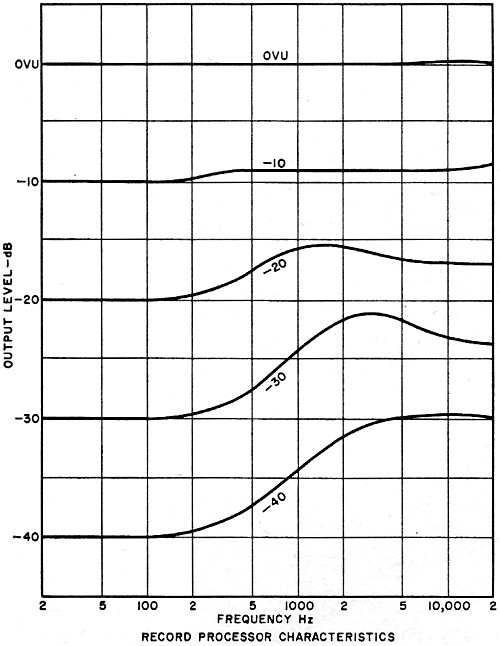
Fig. 2. These are record process characteristics. Playback is
the inverse.
However, not only is the interfering noise reduced at these frequencies. The
desirable music or program content is reduced as well and high-fidelity qualities
are lost. In fact, some attenuation begins to become quite evident at the frequency
where the gain is reduced by 3 dB, or at 1600 Hz in this case.
The situation is improved by using two resistor-capacitor networks so that the
eventual rolloff is at the rate of 12 dB per octave (twice the 6-dB-per-octave rolloff
rate of one network). If the gain at 5000 Hz is reduced by 10 dB with such a circuit,
the frequency at which the attenuation becomes evident (circuit gain reduced by
3 dB) is now about 2100 Hz. This is an improvement over the previous case, but the
output from the amplifier is still badly limited in bandwidth.
One method used to improve the signal-to-noise ratio when recording on tape is
to "ride the gain." A maximum limit on the size of the signal that can be fed to
the record preamplifier is set by the distortion or saturation characteristics of
the tape. Weak signals which might be lost within the tape noise can be increased
manually before being fed to the record amplifier. These signals can be boosted
sufficiently before being recorded so that they can later override the noise during
playback. Average and high-level signals can be manually limited in amplitude when
fed to the recorder so that they will not saturate the tape. These signals are usually
sufficient to mask any tape or record playback amplifier noise similar to them in
frequency.
A variation of this procedure uses an electronic compressor to limit the output
as the gain increases. The relative output-level difference between the loud and
soft passages of music is reduced. Extremely loud passages of music are subdued
so as not to overload the tape or tape amplifiers, while relatively low intensities
of sound are recorded at comparatively higher levels. The opposite of the compressor
- the expander - is placed at the output of the tape recorder to restore normal
amplitude relationships.
One big drawback to this system is the time it takes for the compressor and expander
to go into action. Another defect is "breathing" or noise modulation. Background
noise is alternately increased and decreased, producing very annoying listening
conditions.
Another very successful means of improving the signal-to-noise ratio uses pre-emphasis
and de-emphasis in the recording and playback processes, respectively. Standard
curves specify that the high frequencies be emphasized a fixed amount while recording
on tape. These same frequencies are reduced by an equal amount during the playback
process so that the overall frequency response is level. Noise is overridden by
the large high-frequency signals placed on the tape in the record process and is
reduced during playback due to attenuation of the high end of the band. This system
is used on all tapes and playback equipment that is currently available on the market.
The Dolby System. Perfecting the procedure just described, and
adding some additional brilliant features, Dr. Ray Dolby evolved an excellent method
of reducing noise and hiss, along with any other type of undesirable low-level material
found on tapes.
First, let us state the one thing this method of noise reduction cannot do. It
cannot eliminate noise already recorded on the tape.
Similar to the compressor / expander and pre-emphasis / de-emphasis methods,
the program material must be processed before it enters the recorder electronics
and after it emerges. Here is how the Dolby B-type system used in home recording
equipment works.
However annoying, noise on tape is usually at a much lower level than the music
or other program material. On loud passages, noise is masked by the program material.
You do not hear the noise which may be 40 or 50 dB below the level of the de-sired
sound.
During quiet passages, however, the level of noise is comparable to the level
of the music. It is quite objectionable. The Dolby noise-reduction system discriminates
between loud and soft passages and attenuates noise only when it can be annoying,
as is the case when low levels of material are being reproduced.
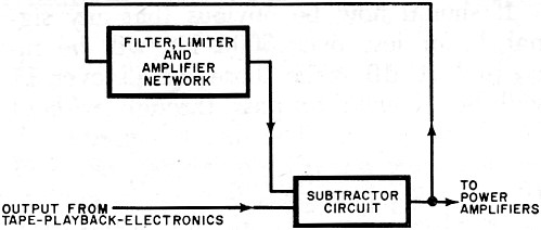
Fig. 3. Dolby output network from recorder has one path through
feedback.
Tape hiss, being a high-frequency phenomenon, is poorly masked by the low frequencies
in the program material, even when the amplitude of the signal is high. Therefore,
the Dolby system separates the high-frequency band from the low frequencies. Large
signals at low frequencies will not keep the high-frequency noise from being attenuated.
Only high-frequency amplitudes determine when noise will or will not be reduced.
Should fixed-filter circuits be used to determine or separate the high-frequency
band from the low frequencies, breathing can become evident. Instead of a fixed
filter, a variable type is used. The frequency characteristic automatically adjusts
itself, by use of a feedback circuit, for the best performance.
Briefly, the input to the tape recorder takes the form shown in Fig. 1. The input
signal follows two paths in the Dolby circuit before being fed to a summing or adder
network. One path is directly to the adder. The second path is through a network
which separates the high-frequency but low-level input signals from the rest of
the material to be recorded. The output of the network is significant above 1 kHz,
rising to its maximum level at 5 kHz and above. The selected signals are amplified
and fed to the adder. The sum of the direct signal and the amplified low-level,
high-frequency signals, is then fed to the input of the tape recorder.
Let us say that the high-frequency filter, for those frequencies above 5000 Hz,
and the level-selective network are actuated when any signal over 5000 Hz falls
to 1% or less of the maximum input signal. This low-amplitude signal will then actuate
the level-selective network and all frequencies of 5000 Hz and above are then amplified
2.16 times. The low-amplitude portion of the signal, instead of being 1% or less
of the maximum input signal, is now 1% +2.16% or 3.16% which is equivalent to increasing
the low-amplitude signals by 10 dB. A compressor-type action is accomplished here
as the low and high levels of the signal feeding the tape recorder approach each
other in amplitude. Even though a wide gap exists between maximum and minimum amplitudes,
the difference is narrowed by a factor of 3.16 or 10 dB. (See Fig. 2)
It should now be obvious that any signal 1% or less over 5000 Hz will be increased
10 dB while those signals over 1% will be allowed to pass through without any Dolby
action. The direct opposite will be true on playback. Any signal that is of 10 dB
level or below will again actuate the level-selective network and, in this case,
attenuate all high frequencies to their previous normal level.
The simple description above implies that the circuit has a sharp threshold at
the 1% level. In practice, as the high-frequency signals rise above the 1% level,
so the amount of boost introduced falls progressively from the 2.16 times. At levels
of -20 dB and above, the boost is negligible, avoiding any over-modulation produced
by higher peak signal levels than normally used.
The output from the preamplifier stages of the tape recorder feeds a network
with frequency characteristics similar to the one at the input (Fig. 3). However,
this time the path is through a subtractor. All the factors added to the signal
by the network in Fig. 1 are now reduced by an equal amount. The original program
material is restored in proper amplitude proportion, expanding the difference between
the high- and low-amplitude portions of the signal. However, noise introduced by
the tape and electronics is reduced by about 10 dB over what it would have been
without the intervening Dolby circuits. The amplified high-frequency signals introduced
at the input of the recorder are capable of overriding much of the noise normally
generated while recording. Reducing gain of these frequencies at the output also
diminishes the audible noise.
Although the system is complex, it can be made as a relatively simple and inexpensive
circuit. The 10-dB reduction in hiss and noise makes it quite worthwhile. When playing
back a Dolbyized tape through conventional equipment, it is only necessary to reduce
the treble response somewhat, using the tone control.
Posted January 25, 2024 (updated from original post on 8/2/2017)
RF Cafe began life in 1996 as "RF Tools" in an AOL screen name web space totaling
2 MB. Its primary purpose was to provide me with ready access to commonly needed
formulas and reference material while performing my work as an RF system and circuit
design engineer. The World Wide Web (Internet) was largely an unknown entity at
the time and bandwidth was a scarce commodity. Dial-up modems blazed along at 14.4 kbps
while tying up your telephone line, and a lady's voice announced "You've Got Mail"
when a new message arrived...
Copyright 1996 - 2026
All trademarks, copyrights, patents, and other rights of ownership to images
and text used on the RF Cafe website are hereby acknowledged.


 by Mannie Horowitz