|
|||||||||||||
 |
|||||||||||||
Phase Noise Description & Equations |
|||||||||||||
|
Phase Noise calculator in RF Cafe's Espresso Engineering Workbook (free).
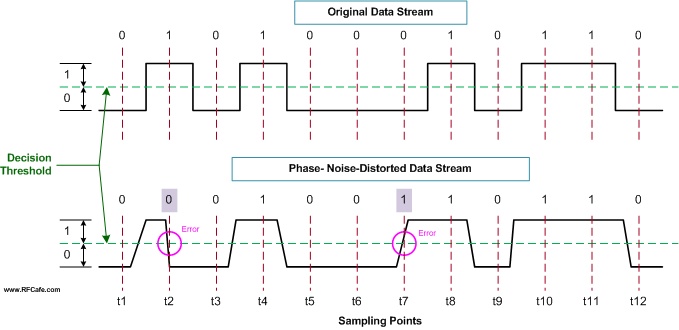
Phase noise measurements quantify the short term stability of a frequency source. That is because phase and frequency are mathematically related by a differential function [ω(t) = dΦ(t)/dt] so they are directly connected. Phase noise also includes amplitude instability due to atomic scale effects like FM flicker noise (1/f3), white noise (1/f2), PM flicker noise (1/f), and possibly even voltage supply noise (typically discrete spurs). When the frequency source is used as a local oscillator in a frequency converter (up- or down-), the amount of instability (jitter) is modulated onto the transmitter or received signal (see drawing).
Phase noise is typically symmetrical about the primary signal (carrier) of a local oscillator so frequency and power values normally references a single sideband (SSB) in a 1 Hz bandwidth. Calculating PLL Phase Noise Based on a Reference Oscillator's Phase Noise
Consider a typical 10 MHz ovenized crystal oscillator (OCXO) shown in graph to the right where I plotted the phase noise of the OCXO in red and the phase noise of a 2 GHz oscillator phase locked to the 10 MHz reference oscillator in blue. You will see that the phase noise of the 2 GHz oscillator is consistently 46 dB [20*log(2*109 / 10*106)] higher than the 10 MHz reference, per the above equation. Because of the multiplication effect, many S-band and higher oscillators use a 100 MHz reference oscillator in order to gain a roughly 20 dB [20*log(10/1)] improvement in phase noise. Use the following equation to calculate the phase noise of a phase-locked oscillator based on the phase noise of the reference oscillator it is locked to: Phase NoisePLL ( ) = Phase NoiseRef + 20*log (fPLL/fRef) {dBc/Hz} Be aware that the equation is theoretical and that a real world PLL will add some of its own intrinsic components to the output phase noise. Differentiating Between Continuous and Discrete Phase Noise
Although not an exact method, you can get a good estimate of continuous phase noise (PNcont.) in a 1 Hz bandwidth by measuring it at a wider RBW and then subtracting the decibel difference based on the ratio of the measurement RBW (RBWmeas.) and the desired 1 Hz bandwidth. Use the following equation. PNcont. in 1 Hz BW = PNcont. in RBWmeas. - 10 * log [RBWmeas. (in Hz)] Example: If you measure -100.0 dBm at a 10 kHz offset frequency when using a RBW of 3 kHz, the continuous phase noise in a 1 Hz bandwidth will be -100.0 dBm - 10 *log (3000) dB = -134.7 dBm During my days as an engineer designing RF systems, I often needed to make phase noise measurements on synthesizers. Back in the early 1990s while working for Comsat I wrote a program in Visual Basic that automatically tested for mixer product spurs in a large batch of synthesizers for use in the INMARSAT earth station transceivers. Time was of the essence, but so was not missing discrete spurs above a prescribed level. If you are familiar with spectrum analyzers, you know that the sweep time is inversely related to the Resolution Bandwidth (RBW) setting, so a larger RBW resulted in a smaller sweep time (faster), and vice versa. The time optimization method I devised started with a wide RBW and checked across the band for violations. If none were identified, the RBW was decreased by one notch and the band was swept again. The loop continued until the noise floor was at or below the maximum permissible discrete spur level. That was the sweep that took the longest (120 seconds on the HP8568B); however, the time savings came from the fact that if a violation was detected at a wider RBW setting (shorter sweep time), the frequency and power was noted and the test was terminated, thereby not performing the longer sweeps. Textbook Phase Noise Composition Equations The following formulas are available in many textbooks and manufacturers' application notes. In reality, very few people really use the equations. Their value to most people is for demonstrating all the components that contribute to phase noise. Note: When using these formulas, be sure to keep dimension units consistent; i.e., do not mix kHz with MHz, mm with inches, etc. It is safer to use base units (e.g., Hz, m) for calculation, then convert result to desired units.
|
|||||||||||||
 |
|||||||||||||
|
|||||||||||||


 , where
 = signal amplitude
 = signal frequency
 = signal phase
 = signal amplitude
variation
= signal amplitude
variation = signal phase
variation
= signal phase
variation

|
||||||||||||||||||||||||||||||||||||


