|
|||||||||||||
 |
|||||||||||||
Selenium Rectifiers
|
|||||||||||||
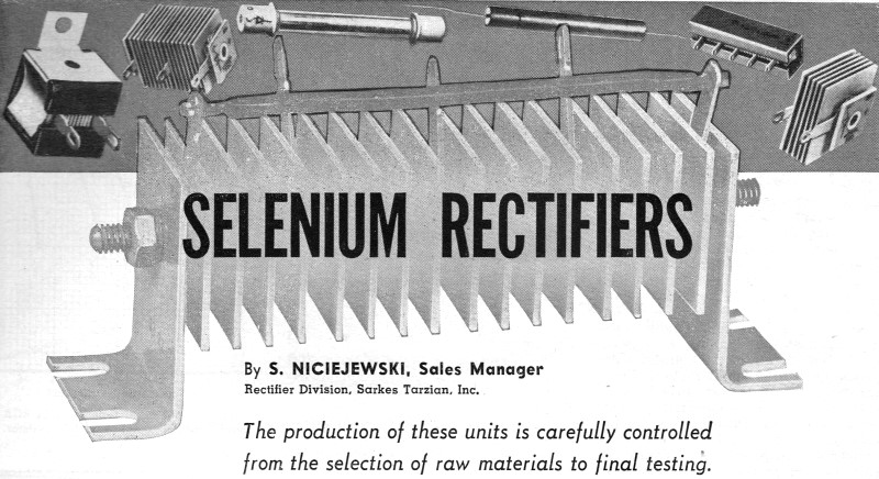
Before silicon and germanium semiconductors came online for use as diode rectifiers, selenium was the material du jour. Selenium devices were widely adopted for use as bridge rectifiers in power supplies and as detectors in AM radios, where applicable, in place of vacuum tubes. At the time, they were not particularly cheaper to implement, but there was an advantage in greater ruggedness, longer lifetime, and lower power consumption (no heater element or high bias voltage required). Electronics magazines of the era published many articles about selenium rectifiers, including After Class: Working with Selenium Rectifiers, The Semiconductor Diode, New Selenium Rectifiers for Home Receivers, Selenium Rectifiers, Applications of Small High-Voltage Selenium Rectifiers, and Using Selenium Rectifiers. Selenium Rectifiers By S. Niciejewski, Sales Manager Rectifier Division, Sarkes Tarzian. Inc.
In appearance, selenium rectifiers are relatively simple devices; however, the process and quality control under which rectifiers are produced are exacting and critical. A one per-cent change in nucleation temperature or an additional few parts per million of impurity in raw materials may disturb the balance enough to produce poor results. The basic materials required are few: selenium, aluminum, and a low melting point alloy; however, the proper application and treatment of these is important. The aluminum is a special alloy that will chemically etch and nickel plate properly in an established process, and the selenium is very nearly 100 per-cent pure; impurities are measured in parts-per-million and the difference between 7 and 10 parts-per-million may result in a poor selenium rectifier. The eutectic alloy used in the counterelectrode is a combination of pure metals that consistently melts at the same temperature. The first step in the process of manufacturing selenium rectifiers is to prepare aluminum base plates by chemical etching and electroplating with a very thin "flash" coat of nickel. The undercut etch serves as a mechanical means of bonding the selenium layer to the base plate during the subsequent pressing operation. The nickel plating governs crystal growth and orientation in the selenium layer. High purity selenium is sprinkled over the nickel plated base plate in fine powder form and is then subjected to high temperature and pressure in hydraulic presses with electrically heated platens. The pressing operation not only causes the selenium to adhere to the base plate but actually starts crystal nucleation in the selenium which is amorphous when applied. This process is very critical and important since poor adhesion of selenium to base plate will have adverse effects on useful life. After the powder-press operation, selenium rectifier cells are placed in long conveyor ovens for heat treatment that completes the crystallization process. Here the selenium is completely converted to "metallic" form and the crystals are arranged to cause rectification. During this heat process the temperature is exceedingly critical; a one per-cent deviation could cause poor crystallization and consequently, a poor rectifier cell. This heat treatment also forms a very thin "barrier layer" on the selenium and it is believed that rectification is accomplished in this layer.
Fig. 1 - How the nonlinear characteristics of selenium rectifiers contribute to high efficiencies even at large overload factors. To produce cells with high inverse voltage ratings it is necessary to expand, artificially, the barrier layer formed during heat treatment. This is accomplished by applying a thin layer of organic lacquer especially developed for this purpose. Under magnification, the artificial barrier layer forms a sponge-like surface, microns thick, that increases the initial reverse or blocking resistance of the rectifier and allows it to be increased even more during later operations. To form a positive contact and current pick-up a low melting-point alloy is sprayed over the barrier layer. The alloys used vary between manufacturers; however, those in common use are alloys that range in melting temperature from 100° C to 175° C. When the alloy is applied the rectifier cell is virtually complete and will efficiently rectify low voltages, approximately 10 volts r.m.s. per cell. However, since most applications require relatively high voltages, the reverse or blocking resistance of the rectifier must be increased substantially to be practical and this is accomplished by subjecting rectifier cells to voltages that cause current to flow in the reverse direction. This process, known as "electroforming," varies slightly, depending on cell size, and usually requires approximately six hours to produce stable cells with acceptable conductive and blocking characteristics. After electroforming, cells are carefully checked for acceptability and placed in stock for assembly into rectifier stacks. For rectifiers normally used in radio and television receivers, stacks are immediately assembled and stocked because some standardization has been reached; however, for commercial power-type rectifiers, stacks are not assembled until orders are received, since most requirements are custom designed and a very large number of combinations is possible. Quality control plays a very important part in the production of selenium rectifiers. Inspection stations are located at every step of the process and numerous tests are made daily. Any indication of inferior quality causes an immediate shutdown of the process line. Also, on completed rectifier stacks, life tests under adverse conditions are continually in progress to determine quality, useful life expectancy, and aging characteristics. Extreme care and control are applied during the manufacture of selenium rectifiers and units shipped into the field are of the highest quality possible to attain; however, in spite of wide application, there are still reports from the field of incorrect application where the rectifier is either caused to fail or is not producing optimum results. It is well at this time to consider a few factors governing the application of selenium rectifiers. Application Notes During the past five years, selenium rectifiers have found application in virtually every phase of electronic and electrical equipment production. Typical applications include radio and television receivers, communications equipment, business machines, battery chargers, electroplating equipment, electrolysis equipment, cathodic protection equipment, guided missiles, magnetic amplifiers, radar and sonar equipment, as well as many special applications. Wherever d.c. power is either required or desirable, selenium rectifiers will provide an economical and efficient method of conversion.
Fig. 2 - How reverse current increases as frequency is varied from 20 to 15,000 cps. In spite of widespread use, the selenium rectifier is still somewhat of a mystery and enigma to the average engineer and technician. Selenium rectifiers are thermally as well as electrically rated devices; therefore, special precautions must be taken to insure long useful life under adverse conditions. The rectifier stack should be mounted with the cells in a vertical plane so that the convection of air is unimpeded. The stack should be mounted at the coolest location on the chassis, away from heat dissipating equipment such as resistors, tubes, transformers, ballasts, or any heat radiating element. If the ambient or surrounding temperature is higher than 50° centigrade, stacks should be properly de-rated to insure long, trouble-free life; however, de-rating is not as severe when relatively short life (1000 hours minimum) is required. Since temperature presents a very complex problem, particular applications should be referred to the manufacturer of selenium rectifiers for individual consideration and recommendation. Following this procedure will always result in the most economical design compatible with life and duty requirements. Table 1 shows general de-rating factors; however, individual requirements may often require deviation from the listed values. To conserve space and decrease weight, many design engineers take advantage of forced air cooling. A sufficient volume of air to limit operating temperatures allows a 250 per-cent increase in d.c. load current. For example, a rectifier that is rated at 10 amperes with normal convection cooling can be operated at 25 amperes if sufficient air is passed between the cells. Also, to decrease the effects of very high ambient temperatures, forced air is often used to allow higher percentages of normal rating. In all cases, the recommendations of the manufacturer should be followed. The efficiency of conversion in selenium rectifiers is relatively high, usually on the order of 90 per-cent in three-phase, full-wave circuits and 70 per-cent in single-phase, full-wave circuits. The nonlinear characteristics of selenium rectifiers contribute to high efficiencies even at large overload factors. For example, in Fig. 1, it is evident that there is only a 10 per-cent decrease in the efficiency of a three-phase, full-wave circuit as the load is varied from 50 per-cent to 300 per-cent of normal, and only 7 per-cent under the same conditions in a single-phase, full-wave circuit. This information is important to the design engineer who plans to use overload factors with forced air cooling.
Table 1 - Derating factors on selenium rectifiers. Note that these factors are based on long life requirements of the units. By the very nature of its construction (two metals separated by a semiconductor) selenium rectifiers have a considerable amount of inherent capacity. This capacity, approximately 0.1 to 0.15 microfarad-per-square-inch of rectifying area, limits the freque-cy at which rectifiers can be used. The practical frequency limit varies between 1000 and 15,000 cycles-per-second, depending on cell size and electrical requirements. In general, in applications that require small values of d.c. current, the maximum practical frequency is 15,000 cycles-per-second; and 1000 cycles-per-second in applications where relatively large d.c. load currents are required. Operation of the rectifier at frequencies above the practical limit results in sharp reduction of the rectification ratio (reverse to forward impedance) and efficiency, due to increased reverse current. Fig. 2 shows the increase in reverse current as the frequency is varied from 20 to 15,000 cycles-per-second. The minimum voltage at which a rectifier will pass measurable amounts of d.c. current in the forward, or conducting, direction is known as the threshold voltage. Depending on temperature, the threshold voltage in a selenium rectifier will vary between approximately 0.25 volt at high temperatures and 0.6 volt at low temperatures. This characteristic excludes the use of selenium rectifiers in applications where very low voltages are required; typical of these are measuring instruments and some control circuits. To insure proper operation and stability the r.m.s. voltage should be a minimum of 1 volt. On the other hand, many applications have been developed around this threshold voltage characteristic and selenium rectifiers are being used as filament voltage regulators and as protective shunts across sensitive instruments. Fig. 3 shows typical isothermal characteristics and values of threshold voltages at various temperatures.
Fig. 3 - Graph of typical isothermal characteristics of selenium rectifiers and threshold voltages at various temperatures. When operated, and to a lesser extent when idle, selenium rectifiers will age; that is, with a constant a.c. input voltage, the rectified d.c. output voltage is higher when the rectifier is first installed than it is after a period of operation. The average decrease in output voltage after 10,000 hours of operation under normal conditions is approximately 5 per-cent, most of which occurs during the first few thousand hours. In applications where the d.c. voltage requirements are extremely critical, the transformer used should be provided with "aging" taps that will increase the a.c. input voltage to the rectifier by 5 to 10 per-cent. By this method any aging of the selenium rectifier can be compensated by increased input voltage. Selenium rectifiers can be overloaded for their current output under momentary or cyclic conditions without serious damage; however, a prolonged overload such as caused by a short circuit will damage the rectifier. Fuses or other protective devices should be used wherever possible and the cause of trouble corrected before power is applied to the rectifier. Overvoltage conditions are more serious than current overloads. A potential in excess of rating may cause a breakdown across the selenium layer and while a selenium rectifier is "self-healing" to an extent, prolonged over-voltage conditions will cause rectifier failure. If an overvoltage condition occurs and the breakdown across the rectifier is sustained the odor of selenium fumes can be detected and power should be turned off immediately to minimize the damage. Cause of the overvoltage condition should be determined and corrected before the power is turned on again. Typical circuits in popular use and a brief explanation of each follows:
Fig - 4. Six common circuits in which selenium rectifiers are used, together with approximate wave shapes under resistive load, ripple frequency, ripple percentage and approximate a.c.-d.c. ratio. (A) Half-wave, single-phase, (B) bridge, single-phase, (C) centertap, single-phase, (D) half-wave, three-phase, (E) bridge, three-phase, and (F) centertap, three-phase. Single Phase Half Wave (Fig. 4A): Half-wave rectification is generally used in applications that require little power. Most popular applications have been in radio and television receivers to deliver "B+" power. The ripple frequency is the same as the supply frequency and the ripple component is large since the rectifier conducts only during one half of the input cycle. Special transformer design is required because of unidirectional flow of d.c. current through the secondary. Bridge (Fig. 4B): The single-phase bridge rectifier is popular because it offers flexibility of design, full-wave rectification, ripple frequency twice source frequency, high efficiency, and utilization of an economical transformer design. Its fields of application cover every phase of electronic and electrical design. Center Tap (Fig. 4C): As in the bridge circuit, the ripple frequency and efficiency are high; however, the transformer design is more complicated. The full-wave, centertap circuit is commonly used in low voltage applications (less than 10 volts d.c.) such as laboratory electroplating and battery charging equipment. Three-Phase Half Wave (Fig. 4D): The three-phase, half-wave connection is primarily used in low voltage high current applications. The output ripple frequency is three times the source frequency and the load ripple component is approximately 20 per-cent. The three-phase, half-wave rectifier is commonly used in commercial electroplating applications that require thousands of amperes of current. Bridge (Fig. 4E); The three-phase bridge is the most economical and useful circuit where d.c. power requirements are high and efficiency is an important factor. The ripple frequency is six times the source frequency and the load ripple component is only 4.5 per-cent. In most applications filtering is not required. Popular applications include aircraft motor starters, electrolysis equipment, large power supplies, and arc welding equipment. Center Tap (Fig. 4F); The three-phase, centertap circuit is used where d.c. voltage requirements do not exceed 15 volts and load current requirements are high. Special transformer design is required to provide a six-phase secondary. This connection is used to some extent in electroplating equipment. In addition to the popular circuits discussed, selenium rectifiers are used in many special applications that take advantage of characteristics peculiar to selenium rectifiers. Typical of these are voltage regulators, spark quenchers, protective shunts, polarizing circuits, magnetic and capacitive field discharge, and d.c. blocking. A few precautions which must be taken when using selenium rectifiers include: 1. Do not use an ohmmeter to test rectifiers. The nonlinear resistance inherent in selenium rectifiers will give erroneous results. 2. Do not loosen the rectifier stack assembly. 3. Take care to keep solder and soldering irons from contacting rectifier cells. 4. Do not install selenium rectifiers with open construction in explosive atmospheres. 5. Even though the rectifier is rugged and can stand abuse, do not subject stacks to severe shock or dropping. 6. Do not expose rectifiers to concentrated mercury vapors. 7. Mount rectifiers away from other heat radiating components . 8. Take8. Take special precautions at extremely high and low temperatures. A good policy to establish is to contact a manufacturer of selenium rectifiers whenever there is any question regarding application or design. Competent engineers and modern laboratory facilities are available to solve your problem.
Posted April 7, 2023 |
|||||||||||||
 |
|||||||||||||
|
|||||||||||||


|
||||||||||||||||||||||||||||||||||||


