|
|||||||||||||
 |
|||||||||||||
Oscillator Squegging
|
|||||||||||||
"Squegging," a phenomenon likened to the rhythmic spurts of a manual water pump, occurs when an oscillator undergoes periodic cycles of oscillation followed by a dead period. This happens when an excessive time constant in the grid circuit, often caused by a faulty resistor or capacitor, drives the tube to cutoff, only for it to restart once the bias bleeds off. In radio and television, this manifests as audible buzzing, intermittent sound, or dark holes in the picture. Historically, the term "squeg" emerged in the specialized fields of radio engineering and electronics during the early 20th century, likely originating as a form of "self-quenching," descriptive of the erratic sounds and pulsatile signal bursts characteristic of the unstable circuit behavior. Whether sinewave-based, multivibrator, or blocking in nature, squegging requires verifying time-constant components or addressing excessive feedback to restore sustained, continuous oscillation and overall signal stability. Oscillator Squegging
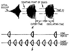
This form of spurious oscillation can produce some puzzling symptoms. By Lucian Palmer The old farmyard pumps produced water in spurts as a result of regular up-and-down motion on the handle. Water did not flow between the spurts (on the handle's upstroke). A squegging oscillator produces a similar output. Fig. 1-a shows squegs (groups or packets of oscillations) with intervening "dead" spaces. There is no oscillation and no output during this dead time. The length of the oscillation period and the dead time are not necessarily equal, but depend on circuit constants, as does the period or repetition frequency of the squegs. This period may be very low, measurable in minutes, or very high and measured in microseconds. Symptoms of Squegging If the local oscillator of a radio set squegs, it punches holes in the sound as if a mechanical chopper had been inserted in the set. This is because no intermediate frequency is produced when there is no oscillation during the dead times of Fig. 1-a. The frequency of the squeg may vary like the quench periods of a superregenerative receiver. The oscillatory packets may close up or spread apart (Fig. 1-b). If the frequency is in the audible range, a radio receiver with a squegging local oscillator will produce sounds varying from a buzz to "plops." A squeg rate above audibility will result in a high hiss level or an increase in noise on a station.
Fig. 1- Squegs are built up in groups or packets that recur regularly; 1-a) typical case of build-up; 1-b) long and short dead times of the oscillator.
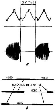
Fig. 2-a) Dead time correlated with video information. The dead time may cover part of a synchronizing period, either horizontal (as shown here) or vertical; b) dead-time symptoms on the picture tube. Successive periods are black. Some may occur during blanking and appear at the finish and start of an active trace.
Fig. 3-a) Oscillatory buildup in tank circuit; 3-b) corresponding grid bias developed; 3-c) characteristic curve showing cutoff and saturation (see text); 3-d) Hartley oscillator circuit for illustration.
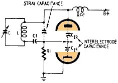
Fig. 4 - Excessive stray capacitance in some oscillators may cause squegging.
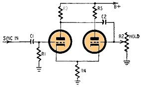
Fig. 5 - Typical cathode-coupled multivibrator circuit to illustrate true and apparent squegs in this type of oscillator. Local-oscillator squegging of a TV front end punches holes in the picture and sound intermediate frequencies. The eye will often see the effects on the picture even though the sound may not seem to be affected. As an example, if the dead period is 10 microseconds, about one-fifth of a horizontal line will be black - due to absence of video information for that part of the 54 sec of active scan. (Unless the squeg occurred in the blanking period, but due the repetitive nature of squegs, succeeding dead times will fall on the active portion of the line.) As dead time increases, some of the dead spots will fall during sync pulse time. The condition is illustrated by Fig. 2. Losing one horizontal pulse now and then will not affect the horizontal sweep stability very much due to the flywheel action of the horizontal afc and horizontal oscillator. But loss of an appreciable portion of the vertical pulse groups will lead to vertical stability impairment (rolling, loss of interlace) far more rapidly. The black spaces in the picture information definitely tie the trouble to squegging though (see Fig. 2 -b). Multivibrators and blocking oscillators may squeg as well as sinewave types. Stoppage of the vertical oscillator results in bright compressed lines where the trace has stopped. The brightness tapers off rapidly, but not immediately, as in conventional retrace and a part of the lower portion of the picture is missing. (The vertical oscillator does not drive itself into retrace but merely stops in this case.) Stopping of the horizontal oscillator results in loss of high voltage in fly-back systems, and no line is visible during the dead period of the squeg. At high rates of squegging, the result may be a flicker. Examination under a magnifying glass will reveal the loss of video information if the local oscillator is at fault, or loss of all line structure if the horizontal oscillator is acting up (due to no high voltage). Causes of Squegging Squegs are caused by circuit conditions that cut the oscillator tube off for a definite time, then turn it on again. The most common cause is periodic cutoff. A grid-capacitor-grid-leak combination with too long a time constant is the most usual reason. Fig. 3 shows how this happens in the Hartley oscillator circuit of Fig. 3-d. Oscillations build up rapidly (Fig. 3-a) and increase the negative grid bias developed across the grid resistor (Fig. 3-b), since the grid is driven positive each cycle and attracts electrons which have to leak off through R1. Increasing charge on the grid capacitor drives the tube to cutoff and holds the grid voltage at or near cutoff until enough electrons have leaked through R1 to permit oscillation to begin again. This is the dead period of Fig. 1-a. The charge of the grid capacitor leaks off and the oscillations start again. The grid bias does not have to return to zero - only to a level that permits oscillations to start. The squeg cycle repeats itself. Increase of the grid resistor value is the most common cause of a too - long time constant. Check with an ohmmeter or shunt the resistor with another. Less common is increase of the grid capacitor. Test by substitution or measurement on a capacitor checker. If an abnormally low value of shunt resistance (across the grid resistor) is needed to stop the squeg, increase in the capacitor is very likely. Too much feedback can cause squegging. In the circuit of Fig. 3-d, the P-part of the tank coil induces a feedback voltage in the G-part. If this is excessive, the height (amplitude) of oscillations shown at Fig. 3-a will result in excessive grid bias (Fig. 3-b) and squegging. Feedback voltage P is dependent on the position of the tap on the tank coil and the gain of the oscillator tube. Excessive B-plus voltage may be the cause - check it with a voltmeter. A new tube may cause a squeg as its mutual conductance may be too great in a critical circuit tubes have a manufacturing tolerance like other components! The tap may have been misplaced ever so slightly in manufacture, so that the number of turns on the P-portion is too great. (A new coil is the usual remedy unless the tap can be moved.) Improper dressing of the leads to tube electrodes (socket terminals) when making other repairs may result in a squeg. Fig. 4 is a typical oscillator circuit found in TV tuners. Feedback is through the interelectrode capacitance between plate and grid. There is some stray capacitance due to tube leads, pins, socket lugs, connecting wires, etc. But if this capacitance is abnormally increased by pushing the connecting wires too close together, a squeg can result. Saturation Squegging In some types of oscillators, the "tube" of Fig. 3-d is plural - the feedback is taken over several stages. Should one of the tubes in the amplifier be driven into saturation and permitted to remain there for a period of time, then squegging will result just as if the tube were cut off. Since plate current cannot change in the saturation region (it is already maximum) no oscillatory feedback can occur and the input voltage on the grid cannot be maintained. Checking the grid bias on all tubes will reveal this condition, which is the result of too positive a bias on one or more grids. It can happen because of a leaking coupling capacitor - one of the more common causes of saturation squegging. Shortwave Oscillators Some local oscillators on shortwave radio sets squeg only on the shortwave bands. A capacitor in series with the grid capacitor may be added to the band-switch in many models to lower the time constant. The added capacitor is necessary on some of the shortwave bands only in most of such cases. Multivibrator Squegging Multivibrators and blocking oscillators may present symptoms resembling squegs that are not true squegs. (Normal blocking oscillator operation is actually a form of controlled squegging.) Any intermittent operation will cause an effect resembling squegging. First, see that the tube itself is not intermittent (substitute). Then check for possible poor contact on the variable resistor that acts as a frequency control (hold control in TV sweep generators). In Fig. 5 for example, intermittency could result from poor contact of the slider arm of R2 (hold) or intermittent opening of C2 (coupling capacitor). Such would resemble squegging with the same symptoms. Increase in value of either C1 or R1 of Fig. 5 will result in a true squeg. So too will appreciable change of the values of R3 and R4, which operate in conjunction with C2 and R2 to flip the multivibrator over. These components control the regeneration or recycling of the right tube. R4 and R5 control recycling of the left tube in addition to the amplification of the tube itself. Blocking oscillators may squeg (apparently) due to any intermittency in their components. As in the case of multivibrators, the time constant of a grid circuit may be altered but this symptom will show up as too low a frequency of sweep just like excessive values of either C2 or R2 in the multivibrator circuit of Fig. 5. Here one has the trouble of low sweep frequency rather than squegging as the symptom. The rather high peak voltages of the waveshapes on components in both multivibrator and blocking oscillator circuits tend to produce intermittents as described above. The best way to be sure is to substitute parts -particularly the capacitors -in such circuits rather than spend too much time trying to locate a defective one. |
|||||||||||||
 |
|||||||||||||
|
|||||||||||||


|
||||||||||||||||||||||||||||||||||||


