|
|||||||||||||
 |
|||||||||||||
Station Design for DX - Part II |
|||||||||||||
Part I of this article appeared in last month's (September 1966) edition of QST, which explains why Fig. 3 is the first one in this article. It introduced concepts in antenna types and siting. This second part talks about cost tradeoffs for various aspects of a DX setup. Author Paul Rockwell does a nice job of providing graphs of cost versus performance increases for transmitter power, antenna gain, tower height and constructions, etc. He uses prices typical of the mid 1960s, but even without knowing the equivalent modern day equipment prices, the shapes of the curves are good indicators of where the point of diminishing returns exists. In 1966, Paul Rockwell wrote a 4-part series for the ARRL's QST magazine on station design for long distance communications (DX) that covered antenna selection and siting (Part I), economics and construction (Part II), Station Configuration and Receiver Topics (Part III), and Propagation Quirks and Operating Tips (Part IV). Part II- Economics of Station Design and Construction Part II By Paul D. Rockwell, W3AFM
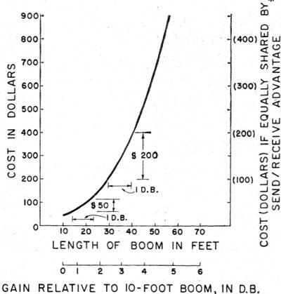
Fig. 3 - Transmitter power costs. In the pursuit of amateur radio, dollar limitations are always present. What is the most practical allocation of available funds? Let us first illustrate an analytical - approach to this question from the standpoint of effective DX-radiated power (DX e.r.p.). Assume 20-meter operation, flat terrain, no voice modulator, and optimum radiation angle of 1°. As a frame of reference, 0-db. will be taken for 100 watts c.w. input, 30-foot tower height, and 10-foot Yagi boom-length. Transmitter power costs run about as shown on Fig. 3. The costs include driver, but exclude v.f.o. The curve would have to be shaded upward for first-class features, and downward for some home constructors. Make your own curve, if you prefer. What is being shown on this and the following curves is a design technique - not a universally applicable set of data. What is important to note, in this example, is that the last db. (from 780 to 1000 watts) costs $100. Now consider antenna costs. Fig. 4 presents these for Yagis. The db. gain values are relative to a half-wave dipole, same height and foreground. The next db. beyond 30-foot boom length costs $200. Stacking two beams, which gives 3-db. gain at the expense of 40-foot additional tower height is attractive beyond about 30-foot boom length. However, this introduces the problem of rotating both beams without interfering with guys. The Telrex Big Bertha solves this by rotating a self-supporting tower. Such a tower, 112 feet high, equipped with antennas and accessories, costs over $15,000 in place. Now tower height. Fig. 5 presents costs, based on $10 per foot for ordinary lattice tower, guys, anchors and foundations. Erection costs are added, beyond 40-foot height, up to $400 for the 150-foot height. No allowance is included for rotator, indicator, insurance, etc. Gains are related to the assumed ideal of 1° takeoff angle by use of the image-antenna geometric construction. Analysis by the indicated technique shows that, to a close approximation, DX e.r.p. at 1° increases as the square of tower height. That is, each time the tower height is doubled, 6-db. improvement is appreciated. Because DX signals often arrive (and should be transmitted) at angles considerably above 1°, this figure must be weighted downward. Fig. 5 has been constructed on the basis of linear relation between e.r.p. and tower height - 3-db. improvement for each doubling of height. This agrees fairly well with Utlaut's results for very high effective heights.
Fig. 4 - Antenna costs.
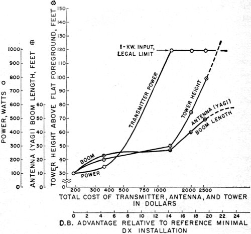
Fig. 5 - Tower Costs. The concept being developed is: Cost per db. for the last db. of improvement which can be handled economically. Suppose we can afford $200 for the last db. By examination of the curves, we see immediately we should run 1-kw. input, for in this department the last db. costs only $100. We choose from Figure 4a boom length of 40 feet. Tower height per Figure 5 is 75 feet. Total cost, adding the corresponding ordinates of Figures 3, 4, and 5 is $1980.00. Perhaps this cost exceeds our means. Maybe we can afford only $50 for the last db. in each of the three departments principally affecting DX effective radiated power (DX e.r.p.). On this basis, we choose 150 watts, 23-foot boom, and 40-foot tower height. Total cost is $350.00. Once the concept is understood, curves may be developed to fit the individual situation, and to take in to account all sorts of other variables: cable losses, fixed costs for auxiliaries, commercial increments of sizes, nested-rhombics-plus-real-estate versus Yagis, etc. An important consideration, so far excluded in order to simplify the discussion, is the fact that antenna db. work both ways: send and receive. Appraisal of antenna and tower costs for DX e.r.p. should therefore be weighted, so as to allocate a share of these costs to the receiving advantage. A reasonable factor is one-half. That is, the dollar values of ordinates of Figs. 4 and 5 can be cut in half, for economic optimization of design with respect to DX e.r.p. only. On this basis, Fig. 6 shows optimum combinations as a function of funds available. The figure is constructed by assuming various dollars-per-last-db. values, and connecting the resultant values by curves. Of course the optimization differs somewhat from the $50/db. and 200/db. examples above, because the receiving components of costs have been broken out separately. For example, suppose $500 are available for the relevant parts of the station. Refer to "Total Cost" on Fig. 6 at $500. Draw a line straight up. Parameters are: Power, 150 watts; Boom, 27 feet; Tower, 50 feet. Gain relative to the reference installation is 5.3 db. If $2000 are available, parameters are: Power, 1 kw.; Boom, 40 feet; Tower, 75 feet. Gain relative to the reference installation is 17.2 db. Fig. 7 presents compatible equipment complements with regard only for DX e.r.p. - no allowance for concurrent receiving advantages. This represents a more conventionally accepted approach. In effect, transmitter power is given greater initial emphasis. These db. are cheap and more convenient than antenna/tower db., but do not bring corresponding receiving advantages. After the legal power limit is reached, optimization proceeds much as on Figure 6. For $500, read off: Power, 275 watt; Boom, 26 feet; Tower, 44 feet: Relative gain, 7.3 db. For $2000: Power, 1 kw.: Boom, 40 feet; Tower, 75 feet; Relative gain, 17.2 db. Economically, c.w. telegraphy gives by far the most DX per dollar. Not only is this true because more DX stations are available by c.w., but also because of greater efficiency, expressed in db. as follows 17: C.w. ............................................ 0 db. D.s.b. a.m., order-wire quality... +17 db. required S.s.b. order-wire quality ........... + 14 db. required S.s.b. DXers will nearly all aver that the table above should be corrected to read "11 db." instead of "14 db" for s.s.b. After reading this, it is fair to ask: "What does a db. in DX e.r.p. really buy, after all, in terms of DX capability'?" The answer is that, other things being equal, it buys a lot. Six db. buy, competitively, a decisive advantage. So far, system-design trade-offs have been discussed. The matter of constructional alternatives is also important in station economics. The remainder of this month's text is on miscellaneous antenna-construction comments. Antenna mounts are frequently the major item of home built equipment.
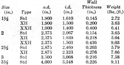
Fig. 6 - Compatible equipment complements (with allowance for receiver advantage). First, re antenna towers. There are fine products on the market. These firms also sell the numerous necessary and desirable accessories: brackets, clamps, clips, anchor, winches, guys, and even gin poles. Only a small percentage of DXers use these products, because the majority (a) can't afford them, and/or (b) home and neighborhood consideration won't permit them. Speaking in generalized terms, short of all-out optimum performance, a practical and almost universally applicable construction is to use telescoping pipe sizes, side-supported to the house, with a hand-winch for running the antenna up and down. This is what is done at W3AFM. Some particulars follow. The cheapest and most universally available mast structural element is water pipe. It comes in 21-foot lengths. It should be ordered black, unthreaded. Local suppliers usually deliver. Prices run about $10.00 a length, depending on weight. Figure 12¢ to 20¢ a pound, depending on discounts, location etc. Sizes are confusing, because they are based on nominal i.d. of the standard weight. "Extra strong" and "double extra strong" are of the same material, but smaller i.d. (same o.d., to match fittings) for greater wall thickness, Some examples are given in the table below, in which "XXH" means "double extra heavy":
Steel much better than water-pipe iron exists. Chrome-molybdenum electroweld or seamless AISI 4142, heat-treated to 180 k.p.s.i. looks great - but costs ten times as much per pound and seems almost impossible to get in less than mill lot. A popular mast in the Northeast is Diamond "E" (1020 cold-drawn steel) 2 inches o.d. by 0.25-inch wall X 20 feet long, selling for about $60.00. So far as known, one of these has never folded.
Fig. 7 - Compatible equipment complements (DX e.r.p, optimization). Aluminum alloys have a modulus one-third that of steel. This can make them very willowy, unless kept short, and thick-walled. In the best installations, the mast or top tubular-section of the antenna-mount, projects only a few feet above the main steel-lattice tower. The rotator is then a few feet below the top of this tower. Sometimes, for reasons previously mentioned, a lattice tower is not practical. In such cases, the pipe mast is extended down to the ground, and the rotator mounted near the ground. Such an antenna support is commonly clamped, loosely so the antenna can be turned, to the side of a house. When this is done, it is important to spread the stress on the house structure. This is done by angle-iron, channels, or wooden members, coupled typically by 1/2 inch threaded bolts all the way through, for example, the attic walls. At W3AFM, a vertical 2 inch X 6 inch X 12 foot plank is bolted to the side of the house, with 2 inch X 4 inch X 6 foot lateral stress-spreaders horizontally inside the attic wall. The strongest wood commonly stocked is oak. Clear white oak, unfinished, and suitably stained, is used. The vertical plank is attached by four 1/2 inch bolts, and projects 4 feet above the peak of the roof. Three husky electrical clamps attach the mast to this plank. The second 21 foot pipe section up from the ground is slotted to fit over a 1/2 inch dowel in the lowermost 21 foot pipe section; so the antenna may be lowered to a height reachable from the roof by first raising it a few inches, then lowering the disengaged part to the ground. Such a load requires work advantage. Boat winches, available from Sears or Ward's at about $25.00, are well suited to this purpose. Half-inch polyethylene boat rope is a good value. It can be dangerous and expensive to economize on small hardware fittings: eyebolts, U-bolts, clamps and the like. Items stocked at Sears, Ward's and neighborhood urban hardware stores generally go only to 3/8 inch sizes, and are cheaply made. For example, a 3/8 inch eyebolt, of the kind having a formed, unwelded eye, if used at the top of the vertical plank mentioned above, could easily unwind and drop the load on the ham below at the boat winch. Where does one get better hardware? Try industrial suppliers, such as McMaster-Carr Supply Co., 2828 North Paulina Street, P.O. Box 4355, Chicago, Illinois 60680. An item not as widely known among amateurs as it should be is the screw anchor. This is a long rod with eye at one end and an auger plate at the other, by which it is screwed in to the ground. A common size is the Hubbard 7526 or Chance 6346, 66 inches long, 3/4 inch rod, 6 inch blade, which sells for about $5.00. Fully screwed into good soil, these withstand 4500-pound pull. Many varieties are made: swamp anchors with blades 15 inches in diameter; rock anchors, etc. A well-stocked supplier is Graybar, with warehouses in most U. S. cities. Graybar also has excellent ground-rods - not as cheap as you see in radio stores - but better. Typical sizes are Hubbard 9348, 5/8 inch in diameter X 8 feet, or Hubbard 9,450, 3/4 inch X 10 feet. They even make one (No. 9697) 1 inch in diameter X 40 feet long. Graybar also stocks clips, clamps, thimbles, arming bolts, eyebolts, shackles, etc. If the terms used above, and other such as: "gin pole," "tag line," and" come-along" are unfamiliar, some preliminary reading or talking with persons having experience in rigging, is desirable prior to undertaking a major antenna project. Alternatively, there are people who, for a fee, will take the problems off your hands. Rescue squads or fire departments which accept public contributions, can be helpful in raising antennas to the top of, say 60, foot towers or poles. A local amateur made a $25.00 contribution (tax deductible?) and found willing and effective cooperation. Raising a tower with a crane can be dangerous, though it is common procedure commercially. A 130 foot, 24 inch tower was once being raised with a 60-foot crane by wiring the tower base to its concrete foundation, and picking up the tower by attaching the crane hook below the tower center. The base temporary wires failed. The tower base whipped sidewise and killed a rigger instantly. Locally, the most experienced ham riggers, W3MSK and W3GRF, prefer to assemble towers such as the AB-105 vertically in place by carrying up pieces, bolting them on, climbing up to the next level, etc., using a light gin pole and ground helpers to pull up materials as required. The reason why self-supported high towers are rare compared to guyed towers, is that they cost several times as much. (The next installment will appear in an early issue.) 17 "Median Signal Power Required for Reception of Radio Transmissions in the Presence of Noise," Technical Report 5, U.S. Army Radio Propagation Agency . .June, 1961. * Costs in parentheses are used for apportionment purposes in construction of Fig. 6. Total costs in all cases are taken from the left ordinate.
Posted Posted July 15, 2021 |
|||||||||||||
 |
|||||||||||||
|
|||||||||||||


|
||||||||||||||||||||||||||||||||||||


