|
|||||||||||||
 |
|||||||||||||
Station Design for DX - Part III |
|||||||||||||
In 1966, Paul Rockwell wrote a 4-part series for the ARRL's QST magazine on station design for long distance communications (DX) that covered antenna selection and siting (Part I), economics and construction (Part II), Station Configuration and Receiver Topics (Part III), and Propagation Quirks and Operating Tips (Part IV). This is part III, which discusses topics such as receiver preamplification, preselectivity and matching, audio and intermediate frequencies. A detailed example block diagram illustrates the various components comprising a typical DX station. Part III - Station Configuration and Receiver Topics
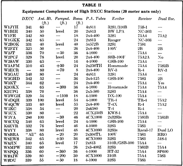
Fig. 8 - 1. Antenna, Yagi. As long a boom and as high as possible (W3AFM: 203C up 45 feet); 2. Rotator: heavy duty, with brake; 3. Low-pass filter, kw. rating; 4. d.p.d.t. coaxial transfer switch, 110 v.a.c. (DK-2-60B); Coil paralleled with tx h.v. "on" control line; 5. Transmit/receive electronic switch (B & W 381); 6. Power amplifier, 1-kw, input, biased to cutoff. (Pair of 250THs); 7. Exciter, with provision for transceive operation with item 11 v.f.o. homemade; 8. Match-box: Johnson 250-30-3; and preamplifier; 9. Bandpass filters, set of 3 covering 14,000-14,105 kc. not installed. Would make preamplifier necessary; 10. Main receiver. Calibration accuracy, ± 0.5 kc. 14,000-04,100. Selectivity: 2 & 0.5 kc. (75A-4). 11. Auxiliary receiver tuned to the station in QSO with DX, for spotting. (75S-3B); 12. WWV receiver. On 5, 10 or 15 Mc. Most anything. W3AFM uses a BC-453 with homemade xtl converter; 13. Digital 24-hour GMT clock. (Tymeter Numechron); 14. A.c. line-voltage regulator. By Paul D. Rockwell, W3AFM The equipment and layout at an amateur station are important factors in its overall performance. Hundreds of different configurations are giving good results. Table II summarizes the set-ups of a sampling of DX stations with outstanding contest achievements, based on returns from a questionnaire earlier this year. Several items are worthy of note. Median antenna height is 74 feet and median boom length is 36 feet. Of the antennas, 96% are Yagis: 4% are quads. There is a preponderance of Eimac tubes and a preference for 4-1000s in the finals. The tabulation gives a good approximation of what sort of equipment complement it takes to be top dog in W/K-land. Not shown, but evident on the questionnaire responses, is that less than 10% of the DXCC stations have electronic break-in at present. Only 20% use preamplifiers, and all of these 20% have antennas below the median height. The configuration at W3AFM, plus a few planned improvements not yet in place, is shown in Fig. 8. Note particularly (a) the use of a second receiver for spotting, and (b) the T/R bypass. The set-up for multiple-band or multiple-operator application needs more than shown here, if it is to do the best possible job. Most of the big, contest-successful stations use separate finals and separate antennas for each band. If they use multiple operators, they provide two or more operating positions. In areas where DX-tip nets exist, such as the LIDXA 2-meter link, an appropriate standby receiver is a must. Receiver Preamplification, Preselectivity and Matching There is a line of reasoning which says that on DX bands, like 20 meters, any good modern receiver has sufficient noise figure to operate effectively without pregain. With respect to sideband operation, this may be true. However, it has repeatedly been observed not to be true, even with receivers of very good repute, on c.w. Apparently the use of sharp-selectivity i.f. filters, accompanied by the use of a nearby notching filter for further narrowing of receiver noise bandwidth and reduction of interference, results in an insertion loss which is more than the receiver can handle. Also, the 20-meter background noise is a random quantity. For some percentage of time, however small, a noise figure as low as 2 db. may permit reception of signals not readable through an n.f. of 10 db. A 10-db. n.f. is typical for many receivers. In any event, a pregain of 20 db., with n.f. of 2 db. has proven advantageous on numerous occasions. Convenient means should be provided for switching the preamplification out during periods when its use aggravates cross-modulation problems to an extent offsetting its advantages.
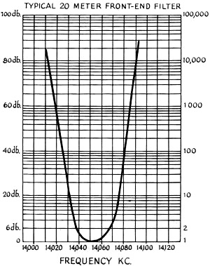
TABLE II - Equipment Complements of High DXCC Stations (20 meter ants only) Particularly in urban areas the subject of preselectivity is often undertreated in station design. In the first place, the use of a low-pass filter between receiver input and antenna may result in a very useful suppression of monkey-chatter due to near-by television stations, or TV receiver local oscillator radiations. Such intermodulation products were sufficient seriously to degrade W3AFM's DX capability. The customary transmitter low-pass filter may of course serve both receive and transmit purposes. Insertion loss of a good low-pass filter is only a fraction of a db. at 20 meters. However, a KW Match-box can serve this and other functions, as described below. Crystal filters at 14 Mc. can pass 30-kc. bandwidths with attenuations less than 6 db., and reject bandwidths exceeding 80 kc. by more than 80 db. Figure 9 shows results measured by C-F networks.18 Manufacturers of such filters have not catered directly to the amateur market because of high engineering costs. Helical resonators19 invite application. Operating Qs of the order of 1000 can be obtained in moderate volumes. That is, in about four cubic feet, using this design technique, it is possible to construct a tunable preselector having, say 14-kc. nose bandwidth at 14 Mc. Urban operating conditions, made less than pleasurable by receiver overload from nearby signals, can be greatly improved by attention to preselectivity. Even clean signals, in a radius of a couple of miles, and offset more than 50 kc. in frequency, can hurt DX reception. Modern techniques can reduce the trouble-radius from a couple of miles to a couple of city blocks. Receiver matching to the antenna has been known to yield as much as 6-db. improvement in signal-to-noise ratio. Even if the antenna is matched 1:1 at the feeder connection, there can be (and often is) a serious mismatch to down-coming energy at the receiver input-terminals. Energy reflected from this point to a matched antenna never comes back - it is re-radiated. This may account, in certain situations, for a part of the effectiveness of low-noise-figure pregain.20 Some amateurs prefer to use a low-loss matching network at the receiver terminals, omitting preamplification." This is effective if (a) the receiver happens to need it, and (b) the matching network is extremely low-loss. An enclosure no smaller than one cubic foot, and large, high Q coils should be used. Construction as for transmitting use22 may do. A.F. Selectivity In c. w. work there is no need to pass audio frequencies outside the band 300-800 c.p.s. As sharp a roll-off as practical is recommended. A simple expedient is to put an oil capacitor in series with the loudspeaker voice-coil. The loudspeaker at W3AFM seems to resonate around 800 c.p.s. with 10 mf. in series. For earphones, a pair of old ones with natural resonance (Weco CW 49003) are employed.23 Five-inch trumpets aren't bad.
Fig. 9 - The results measured by crystal front-end filter networks. I.F. Selectivity For routine c.w. operation, a 500-c.p.s. mechanical filter is ideal. For special situations, 2-kc. and 200-c.p.s. filters should be available. The 2-kc. filter is used for wobbly signals, and sometimes for net standby. The 200-c.p.s. crystal-lattice filter is for QRM situations and "digging in." The 200- and 500- c.p.s. filters are used, in the end, about half the time each. use of the 2-kc. filter is almost negligible, and it could be done without. On both the 75A4 and 75S3B receivers, it has been observed that readability of threshold c.w. signals is improved by use of the "Rejection Tuning" notch filter, accompanied, of course, by careful optimization of b.f.o. frequency. Careful adjustments of these two controls call bring in a signal otherwise unreadable. The notch-filter, in this sense, is not being used in its intended purpose of rejecting an interfering carrier. Rather, it shades the channel noise-response and improves both sin ratio and signal readability. This is true both on 200- and 500- c.p.s. filters. Filters of 100-c.p.s. bandwidth, 455-kc. center-frequency, are now available. The 8-crystal, 1/2-db, Tschebycheff (i.e., 1/2-db ripple) response filter has attractive characteristics but seems impractical at present because (a) it is not in production; so costs are high (b) few, if any, receivers have sufficient interstage shielding to take advantage of the skirt-selectivity of such filters, and (c) questions of nose shape and ultimately-useful narrowness are not yet clearly established. It is feasible to make 455-kc. crystal-lattice filters with 10-c.p.s. bandwidth and steep skirt-selectivity, for example - but the practical usefulness is very doubtful. Keying pulses are rounded, making them difficult to copy at bandwidths approaching F, where F is equivalent frequency of the shortest keying pulse. For manual telegraphy, F (c.p.s.) = w.p.m. is a useful approximation. From this, 20 c.p.s. would be near the ultimate. Drift of distant-end and local oscillators, ease of tuning, and psycho-otological factors indicate this is too narrow for practical application. W4KFC finds, with a 75A2 receiver, he gets best results with tandem use of a 500-cycle mechanical filter and a single-crystal filter-stage (No. 1 position on the 75A2). For c.w. operation only, a recommended combination is to build in a 500-cycle filter i.f, stage, then precede this with a stage having options for narrower selectivities. For example, insert a 500-c.p.s. mechanical filter between 1st and 2nd i.f. stages and a 200-c.p.s. filter between the mixer and 1st i.f. stage. Thus the limitations of interstage shielding are improved from, say, 50 db. to 100 db. with respect to skirt rejection. Receiver Dynamic Range The exploitation of i.f. and a.f.. selectivity advantages (as opposed to pre-receiver r.f. selectivity ) is seriously inhibited by dynamic-range limitations in all present-day receiver designs. There is no use building in 100-db. rejection to outband signals, if, as is often the case, a few of them can get together and drop cross-products only 40 db. down squarely in the passband. Present-day station-design provisions are (a) pre-selectivity (b) pregain gain-control, usually by simply switching the preamplifier in/out, and (c) use of 7360 or equivalent mixers. Naturally, one uses as little r.f. gain as possible during interference conditions, and the receiver must have a separate r.f. gain control for this adjustment. The 75A4 Receiver Some DXers of proven good judgment hold that the 75A4, suitably modified, is the best receiver ever made. The simplest modifications are: (1) Remove i.f. shunt resistors R46 and R29 (2) Remove a.f. feedback resistors R71 and R109. Substitute 820K for R109. More complicated steps are: (3) Install 7360 mixers per QST, July, 1964, p. 18. (4) Install 6GM6 or 6EH7 stage with appropriate cathode and a.g.c. arrangements. Reported results are: 12-db. improvement in sensitivity, better dynamic range (less nearby-signal overload problem), and less hum. Some experienced 75A4 modifiers (W2JT, K3OKX and W2VCZ) prefer a 12AT7 first mixer (presumably per 73 Magazine. Oct. 1961, p. 32) and 6EAS second mixer (presumably per CQ, June, 1960, p. 81, which is for the earlier 6USA). The 7360 modification is complicated. Serial numbers of 4200 and over are prized by 75A4 connoisseurs. These are the latest production version, and include the very-worthwhile vernier tuning knob. They may be recognized instantly by the lettering, upper right-hand corner of the front panel, Noise Liiter and AM CW-SSB all being on the same horizontal line. A difficulty that occasionally occurs with aging 75A4s is p.t.o. instability. It is characterized by a lurch of one to five kc. This is especially noticeable because, when good, the receivers are paragons of frequency stability. Some steps to correct PTOs: (1) New 6BA6s, V-14 & V-15; OA2, V-18; and 5Y3, V-17. (2) Replace C205, 51 pf. This can be done without removing p.t.o. (3) Loosen p.t.o. mounting screws. Manually wiggle to relieve stresses. Retighten softly. (4) Lubricate p.t.o. front bearing. (5) Wring out 8 holes, 1 inch diameter, on the bottom cover plate under p.t.o. to ventilate. Replace 5Y3 with silicon plug-in. (6) Replace the padder, and (especially) the temperature compensators. If it reaches the point of Step (6), it's worth their fee (currently $46.00) to send the 70E24 back to Collins Cedar Rapids for turn-around. They have a temperature-cycling and calibration jig.
18: Meyer, "Front-End Crystal Filters for Amateur Radio Use, Interadio (annual publication of the International Amateur Radio Club, (Geneva) 1965, p. 60. 19: McAlpine and Schildknecht, Electronics, Aug. 12, 1960, p.140. 20: For very-low-noise receivers the input is customarily mismatched to optimize noise figure. See Vacuum Tube Amplifiers, Valley and Wallman, McGraw-Hill, 1948, or "Low-Noise Amplifier," Wallman et al, PIRE, 1948, p. 700. The arguments for control of input coupling are still valid. 21: From W6AM: "The hams hereabouts find a Johnson KW Matchbox placed conveniently next to the receiver for receiving-only improves s/n. The 275-watt Matchbox doesn't work as well. Four attempts at making smaller receiver-type Matchboxes failed to equal the Johnson. Apparently the large shielded box and large silver-plated coil do the job better than anything smaller. The receiver tap is moved from the 300-ohm position to the transmit 72-ohm position. This KWMatcbbox has proved far more satisfactory than preamplifiers for a number of local DX hams," 22: McCoy, "A Completely Flexible Transmatch for One Watt to 1000," QST, June 1964, p. 39; and "A Versatile Transmatch," QST, July 1965, p. 58. 23: See also W6EUM, 73, July 1962, p. 58.
Posted September 7, 2021 |
|||||||||||||
 |
|||||||||||||
|
|||||||||||||


|
||||||||||||||||||||||||||||||||||||


