|
|||||||||||||
 |
|||||||||||||
The Stabistor Diode
|
|||||||||||||
The Stabistor, a specialized semiconductor device introduced in the 1960s, functions as a voltage-dependent switch that remains an open circuit until its specific "break over" voltage is reached, at which point it conducts current effectively. Popular Electronics magazine highlighted its versatility, showcasing practical circuits for sensitive meter overload protection, linear temperature-sensing bridges, signal volume compressors, noise-squelching limiters, and voltage regulation. By utilizing the forward conduction characteristics of silicon junctions, the Stabistor provided a cost-effective alternative to more complex components of the era. Despite its utility, the Stabistor is largely obsolete today. Modern integrated circuits and low-cost, high-precision Zener diodes or standard silicon diode arrays have surpassed its performance and availability. Advances in semiconductor manufacturing have enabled engineers to integrate these protective and regulatory functions directly into silicon chips, rendering discrete Stabistor components unnecessary for contemporary electronic design, as superior, more compact alternatives now handle signal limiting and voltage referencing with greater efficiency and reliability.
The Stabistor Diode
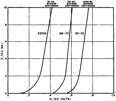
Fig. 1 - Stabistor characteristic curves for three Transitron types. Never exceed the maximum continuous current ratings. Intermittent peak current ratings are about four times higher. By R. J. Shaughnessy One of the newest members of the semiconductor family, the Stabistor has many interesting and practical applications. Since the introduction. of the transistor, the semiconductor industry has produced a miscellany of fascinating devices from double-anode Zener diodes to multiple -layer solid thyratrons. While the technician, serviceman or experimenter is interested -in such new developments, he seldom finds them adaptable to his personal needs. In a great many of the cases where they do apply, their cost is prohibitive. But the "Stabistor," still another addition to the growing semiconductor list, is an inexpensive device with application possibilities that are endless. The Stabistor is a diode designed to "break over" and conduct at 'a certain voltage. This is the normal forward conduction of a diode also characteristic of Zener diodes which avalanche into conduction when a breakdown (backward) voltage is exceeded. Figure 1 (on next page) shows the characteristics of three Stabistors presently available from the manufacturer (Transitron Electronic Corp., 168 Albion St., Wakefield, Mass.).
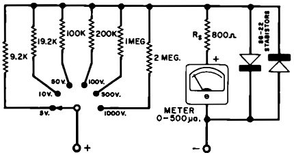
Fig. 2 - Stabistor-protected multirange d.c. voltmeter uses 1% resistors for accuracy. Two Stabistors are employed to protect against reversal of probes as well as overloads.
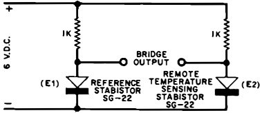
Fig. 3 - Temperature-sensitive Stabistor bridge has linear voltage output with respect to change in temperature. The bridge supply voltage may vary as much as 20% and still maintain constant output.
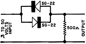
Fig. 4 - Stabistor volume compressor circuit.
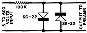
Fig. 5 - Voltage limiter circuit using Stabistor diodes.
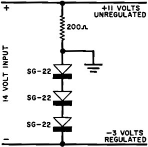
Fig. 6 - Stabistor voltage regulator using a diode stack. You can see that each curve strikes the voltage axis at a small positive voltage, approximately 0.2, 0.4, 0.6 volt, depending on the Stabistor. Below these voltages the Stabistors do not conduct, as shown by the zero voltage line crossing the zero current line. This means that a Stabistor's junction is an open circuit until the voltage across it reaches the "break over" potential and then it is practically a "short." How can we use this feature? Well, why not put the Stabistor across a sensitive meter and let it work as an overload protection device. You'll remember that fuses are put in series with the loads they protect. But in the case of the Stabistor, the infinite resistance characteristic below the "break over" voltage will not affect the meter reading when the Stabistor is across the meter. When the voltage applied to the meter becomes high enough to damage it, the Stabistor will start conducting and "bypass" the excessive current, thus protecting the meter. You can use a pair of Stabistors connected in parallel and back-to-back across the meter movement as shown in Fig. 2 to build a burn-out-proof voltmeter. This arrangement of Stabistors has the added advantage of protecting the movement against any damage that might result from an accidental reversal of the test leads. Or you can build an interesting temperature-sensitive bridge using a Stabistor as the sensing element, as shown in Fig. 3. Voltages E1 and E2 are within a few millivolts of each other and a temperature change in the sensing Stabistor causes a linear voltage change across the output terminals. Possible uses for such a bridge include probing the throats of multi-carburetor or sports car engines for intake temperature matching, checking equipment cabinets for hot spots, and indoor-outdoor thermometers. The Stabistor volume compressor circuit shown in Fig. 4 has an output that increases only .1 volt for a 20 db increase at the input. In this way, a wide dynamic range of input signals can be applied to a preamplifier without fear of overload. If you need a squelch in. your receiver, try the Stabistor limiter circuit shown in, Fig. 5. Weak background noise and static at the input below .3 volt will be attenuated more than 40 db at the output. Desired signals over .5 volt will "pass through" easily with a dynamic loss of only 6 db. Figure 6 illustrates still another application for Stabistors - a regulated voltage divider-With this setup, you can get a positive and negative output from your transistor power source using only three Stabistors; regulation of the 3-volt output will be maintained within 1% for input voltage changes of 15%. |
|||||||||||||
 |
|||||||||||||
|
|||||||||||||


|
||||||||||||||||||||||||||||||||||||


