|
|||||||||||||
 |
|||||||||||||
Antennas for Satellite Reception
|
|||||||||||||
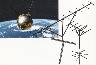
This 1958 Popular Electronics magazine article provides practical instructions for constructing high-gain antennas to receive 108-MHz satellite signals, detailing four designs ranging from simple folded dipoles to complex Yagi arrays. The author emphasizes that success requires precise impedance matching, careful orientation, and weatherproofing, often utilizing modified television hardware to capture weak transmissions from early space vehicles. While the fundamental RF physics of signal gain and directivity remain unchanged, "listening" to satellites today has shifted from manual, labor-intensive construction of metal arrays to the use of Software Defined Radios (SDRs) and automated digital tracking systems. This modern approach replaces the mechanical challenges of manually aiming antennas and compensating for atmospheric effects with high-speed digital processing, allowing hobbyists to decode complex telemetry and imagery that would have been inaccessible to the average listener in the 1950s. Antennas for Satellite Reception
Four different types allow you to choose the best for your location.
AI-enhanced version. By William I. Orr, W6SA1 The key to success in satellite reception is two -fold: a good receiver and a good antenna. A converter that works in conjunction with your short-wave receiver to provide 108-mc. reception was described in detail in the April issue of Popular Electronics. To complete the picture, here are some inexpensive, efficient antennas you can build that will work with that converter, or with any other 108-mc. converter or receiver. Simple Dipole Antenna If you live in the southern part of the United States, the satellites launched from the Florida site will pass almost over your head. Signals from the miniature radio transmitters aboard these pioneer space vehicles should be loud and strong. If you are further north, the signals will be weaker, as the satellites are at a greater distance from you and lower on your optical horizon. For those listeners living under the sweep of a satellite, a simple folded-dipole antenna might suffice to pick up a strong signal. A suitable folded dipole can be made from a short length of 300 -ohm, TV "ribbon" lead-in, as shown in Fig. 1. The antenna element is a piece of ribbon cut to resonate at 108 mc. Twist the two copper wires of the ribbon together at each end and solder as shown. One of the two parallel wires should be cut at the exact Center of the antenna, and each "leg" soldered to one wire of a random length of ribbon line that serves as the lead-in. This dipole can be tacked to a light piece of wood which is mounted in a horizontal position atop a short mast. Make the installation high enough so that it is in the clear and free of nearby metallic objects, such as tin roofs, drain pipes, etc. The horizontal portion of the antenna should run east and west for maximum signal pickup from satellites launched in an east-west direction.
Fig. 1 - Simple folded dipole is mounted horizontally and in the clear. Solder and tape all joints.
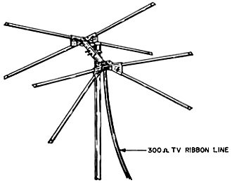
Fig. 2 - This TV conical antenna can be used for satellite reception without alteration. It is available with roof-mounting or chimney-mounting accessories.
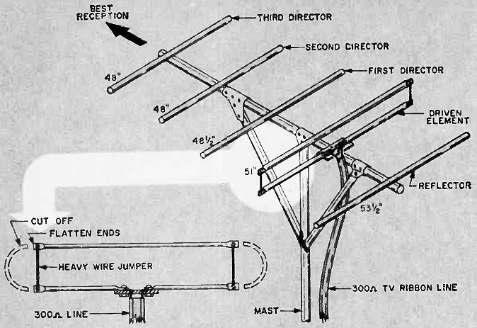
Fig. 3 - Channel-6 TV Yagi antenna cut down for 108 mc. will provide more gain than a conical antenna or a folded dipole. Elements are cut to the new over-all lengths shown.
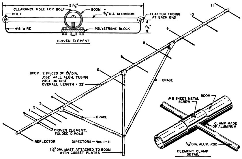
Fig. 4 - A long long Yagi, with 13 elements on a 32' boom, has 16 db forward gain.
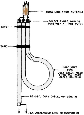
Fig. 5 - Balun transformer at receiver provides an impedance change of 4:1 and is used to connect a balanced termination to an unbalanced one. Bring the ribbon lead-in into your house, just as you would the usual TV-type lead-in. A simple matching device (to be described later) should be used to couple the lead-in to your satellite receiver or converter. Adapting a TV Antenna Listeners in the central part of the U. S. should arm themselves with a more efficient antenna than a folded dipole. As the signals will be weaker, a boost in signal pickup will be of much help in hearing the flying radio stations. Readily available through most television parts distributors is the well-known and popular all-channel conical TV antenna shown in Fig. 2. It provides a substantial signal gain over the simple dipole and may be used for 108-mc. reception without alteration. A single-bay conical antenna can "double ín brass" for TV reception. The conical antenna should be installed in the manner described for the dipole, and pointed southward for preliminary reception tests. After the satellite signal is found, it can be oriented for optimum reception. A simple matching system is also required at the receiver or converter for best performance. TV Yagi Antennas The best results in marginal reception areas can be obtained from a Yagi parasitic antenna array. It is composed of a single pickup element placed in line with a number of parasitic elements which provide a high degree of signal gain, covering a relatively small area in front of the antenna. Because of the high directivity, you have to aim the Yagi beam antenna at the path of the onrushing satellite (Fig. 3). As the width of the pattern of optimum reception is roughly inversely proportional to the signal gain of the antenna, the larger arrays require careful positioning. An inexpensive antenna can be made from a cut-down channel-6 Yagi television array. Either a 5-element or a 10-element Yagi can be used, the larger assembly providing the greater signal gain. Trim the lengths of the elements to move their resonant frequency from channel 6 (about 83.25 mc.) to the satellite channel. A few minutes work with tin snips or hacksaw can complete the job. Trim equal lengths off the tips of each element to change the operating frequency. The new over-all dimensions (tip-to-tip) for a 5-element array are shown in Fig. 3. Each element should be trimmed so that both sides are of equal length. The folded dipole may be cut at each end and the extra U-section at the tips discarded. Flatten the ends of the tubes with a hammer and drill for 6-32 bolts. Place short lengths of heavy copper wire between the bolts to complete connection at the element tips. This Yagi antenna is fed with 300-ohm ribbon line in conjunction with the balancing unit to be described. For initial reception, the antenna should be pointed to the south and oriented for best reception of the satellite as it passes the vicinity of your receiver. A cut-down 10-element channel-6 Yagi will provide more signal pickup than the 5-element beam. The price that must be paid for the higher gain is the disadvantage of a sharper pickup pattern which is about 25° wide on either side of the axis of the boom. This Yagi must be "aimed" at the satellite with a fair degree of accuracy. It probably will be necessary to vary its position for best pickup. No element dimensions can be provided for a Yagi array of this length as optimum performance is dependent upon a combination of factors, such as interelement spacing, element lengths and diameters. Since these dimensions vary from one make of Yagi to another, a general procedure applicable to all antennas of this type must be employed. A satisfactory process is to apply a reduction ratio to the original dimensions. The spacing and diameter of the elements can remain unchanged but the over-all element lengths must be shortened by the ratio of the contemplated frequency to the original frequency of antenna operation. As the design frequency is 83.25 mc. in this case, and the satellite frequency is 108 mc., each element must be shortened in length by a factor of 83.25 / 108. For example, if the driven element of the Yagi is 63 1/2" long, it must be trimmed to 63½ x 83.25 / 108 or 49". The folded dipole can be cut and trimmed as described for the 5-element Yagi. A 300-ohm lead-in and the balancing unit should also be used. The Long Long Yagi In areas of marginal reception, or where the strongest possible signal is desired, an extended Yagi antenna should be employed, such as the 13-element unit shown in Fig. 4. This home-built long long Yagi is designed for highest possible gain at 108 mc. Element lengths, interelement spacing, and element diameters are chosen to provide a power gain figure greater than 16 db at operating frequency. This is equivalent to an increase in power of the satellite transmitter by a factor of 40! As the effective beam pattern of maximum signal gain is only about 15° on either side of the axis of the boom, care must be taken in orienting the antenna for maximum signal strength. Eleven parasitic directors of uniform length are resonated for maximum signal pickup over a frequency span covering 107 - 108.5 mc. This range encompasses any auxiliary telemetering channels that may be adjacent to the 108-mc. center frequency of satellite transmission. All dimensions in Fig. 4 should be copied closely as this Yagi is critically tuned. The structure is a metal supporting frame (or boom) through which the various elements are affixed. Make the boom out of two pieces of 11" aluminum tubing having an 0.0625"-thick wall. This tubing is rigid enough to prevent the array from flexing in a heavy wind. Brace boom to mast with two lighter sections of tubing. Cut 11 directors and one reflector from lengths of 3/6"-diameter rod or tubing. Smooth and buff the ends of these elements to the correct length, then pass each element through an oversize 1/16" hole drilled horizontally through the body of the boom. The element is centered in the hole as shown, and a simple clamp made from a sheet metal screw and a scrap of aluminum holds it securely to the boom. Care should be taken when the boom is drilled to make sure that all the element mounting holes lie in the same plane, or the completed array will have an unkempt air about it. It is best to drill all element holes at one time. Use a drill press and a bench vise if you can, and it will be a simple job. Make the driven element of the long long Yagi out of a length of 5/8"-diameter aluminum tubing passed through clearance holes drilled in the boom. Use a plated 6-32 nut and bolt to clamp the element to the boom. After the element is passed through the boom, carefully flatten the ends and drill for 6-32 plated bolts. Be sure to use plated or galvanized hardware at all points as untreated hardware will rust in damp air. The remaining portion of the driven element is made of two lengths of #8 enamel copper wire. Clean one end of each length of the enamel and wrap it around the bolt placed at the tip of the element. A nut and lock washer will hold the wire firmly in place. Bend the two sections of wire back along the aluminum tubing, maintaining a spacing of 1¼" from the tubing. Clean the ends of the wires and wrap them around the two 6-32 mounting bolts that are passed through á small piece of polystyrene, Lucite, or similar insulating material held in position by the nut and bolt that lock the driven element to the boom. Attach the "ribbon" feedline to the driven element at these two bolts. Upon completion, attach the antenna to the top of a TV-type mast or other support with the aid of two gusset plates cut from aluminum. Bolt the plates to the top of the from a half-wave length of coaxial line placed across the terminals of the 300-ohm ribbon at the point where it is attached to the input terminals of the receiver. It is cut to a length of 35½", resonating it to 108 mc. When placed in shunt with the 300-ohm line, it provides an unbalanced termination of 75 ohms, suitable for most converters. Once trimmed to length, the balancing transformer is inserted in the antenna circuit and forgotten. Installing Your Antenna Mount your satellite antenna in the clear, above nearby metallic objects and adjacent antennas. Television-type masts and hardware may be used to place the array in position. Suitable hardware for roof and chimney mounts can be purchased from almost any TV dealer or radio distributor. Regardless of the type of mount, the antenna assembly must be protected from inclement-weather and corrosive moisture in the atmosphere. If it is installed near the sea coast, the salt-laden air will soon play havoc with its aluminum portions. To retard corrosion, the boom of the array can be given a coat of aluminum paint or other protective covering. The elements of the array must be treated with caution, particularly in the case of the long long Yagi. A coating of paint or other thick insulating substance will detune the elements to such a degree that effectiveness is largely lost. The new Krylon plastic spray may be used on the elements to provide a clear, tough coat of waterproof acrylic compound. Sprayed on under pressure, it will prevent rusting and pitting. and will make them salt-spray-resistant. The whole antenna and supporting boom could be sprayed. If you want to track the satellite, the antenna can be supported and rotated by a TV-style rotator. This will come in handy for making tape recordings of the signal or for studying the Doppler shift. Of several suitable rotators, the Cornell-Dubilier TR16 has been used for this type of work with good results as it has a remote direction indicator and an instant-locking mechanical brake. |
|||||||||||||
 |
|||||||||||||
|
|||||||||||||


|
||||||||||||||||||||||||||||||||||||


