Here is the "Electricity - Basic Navy Training Courses"
(NAVPERS 10622) in its entirety. It should provide one of the Internet's
best resources for people seeking a basic electricity course - complete with examples
worked out. See
copyright. See
Table of
Contents. • U.S. Government Printing Office; 1945 - 618779
Some of the NAVPERS course content needed to be updated as technology and knowledge
evolved. For instance, what is usually referred to as "conventional current flow"
is defined as being a positive charge moving from the more positive point to the
more negative point in a circuit. We now know that it is electrons that constitute
current flow and they move from the more negative point to the more positive point
in a circuit. So, when you see current flow arrows leaving the source's positive
terminal and reentering the negative terminal, it is "conventional flow."
Conversely, when you see current flow arrows leaving the source's negative terminal
and reentering the positive terminal, it is "electron flow." It is an
important distinction to make when considering magnetic fields generated by current
flow, and induced current from a changing magnetic field (see
Right-Hand
Rule page on RF Cafe.
Chapter 13: Induction - Magnetism to Electricity
 In the last chapter you witnessed the production
of a MAGNETIC FIELD by an ELECTRIC current. This illustrated one-half of the tie-up between
electricity and magnetism. The other half of the picture is the production of an ELECTRIC
current by a MAGNETIC FIELD. In the last chapter you witnessed the production
of a MAGNETIC FIELD by an ELECTRIC current. This illustrated one-half of the tie-up between
electricity and magnetism. The other half of the picture is the production of an ELECTRIC
current by a MAGNETIC FIELD.
How It's Done
Set up a magnetic field from a horseshoe magnet-cut through this field with a conductor.
A voltage is induced in the conductor. That's the gist of producing a current from magnetism.
But, for a complete understanding of this process, you'll have to first know something
about a GALVANOMETER. The galvanometer is a sensitive meter which. measures very
small currents. It is used instead of an ammeter when the value of current is small enough
to be measured in microamperes or milliamperes. You would use this instrument to measure
the small current produced in cutting the field of ONE magnet with ONE conductor.
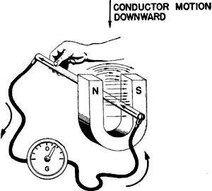
Figure 106. - Inducing EMF-downward motion.
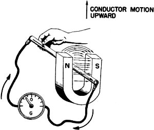
Figure 107. - Inducing EMF-upward motion.

Figure 108. - Magnetic field reversal-induced EMF reversed.
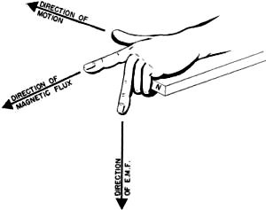
Figure 109. - Fingers in the generator left hand rule.
Set up the circuit shown in figure 106 - you are ready to produce a current from magnetism.
notice that when the conductor is forced DoWNWARD through the field, the galvanometer
is deflected to the right, which indicates that the current of the conductor is IN. Now,
as in figure 107, force the conductor UPWARD through the magnetic field. The galvanometer
is deflected to the left, which indicates that the current of the conductor is OUT. The
fact that the direction of galvanometer deflection REVERSES for a reversal of the direction
of flux cutting by the conductor shows that -
the DIRECTION OF the INDUCED current DEPENDS ON the DIRECTION OF FLUX CUTTING.
currents which are produced by a conductor cutting magnetic lines are called INDUCED
currentS. Actually it is not current which is induced. nothing can create current because
current is electrons and electrons are matter. You cannot CREATE nor DESTROY matter.
What really happened is this - cutting the lines of force transferred some of the magnetic
energy to the conductor. This energy then became an EMF - an INDUCED EMF. The induced
EMF forced the electrons (already in the wire) to flow. It's perfectly OK to call it
INDUCED current so long as the EMF is INDUCED EMF. Most electricians make use of the
term "induced current" and it has become pretty well accepted. Just another one of those
things!
Compare A and B of figure 108. These diagrams differ in two ways -
(1) A has the N pole on the left and B has the N pole on the right. This
means that flux is traveling to the right in A and to the left in B. Check it!
(2) The induced current in A is IN and the induced current in B is OUT.
Connect these two items together and you have-
the DIRECTION OF the INDUCED current DEPENDS ON the DIRECTION OF the MAGNETIC FIELD.
This makes three "directions" involved in the process of inducing an EMF -
(1) The direction of the CONDUCTOR in cutting flux.
(2) The direction of the FLUX FIELD.
(3) The direction of the INDUCED EMF.
All three "directions" are interdependent, and are connected together by another hand
rule - the generator hand rule. The GENERATOR HAND RULE states -
PLACE the THUMB, FIRST, AND MIDDLE FINGERS OF the LEFT HAND ALL AT RIGHT ANGLES TO
EACH OTHER (Figure 109). Now, the FIRST FINGER POINTS IN the FLUX DIRECTION, the THUMB
POINTS IN the DIRECTION OF the MOTION OF the CONDUCTOR, AND the MIDDLE FINGER POINTS
IN the DIRECTION OF the INDUCED EMF.
Figure 110 illustrates three examples of changing one of the directions. note that
the direction of EMF changes every time either the conductor motion or the magnetic field
changes direction.
The generator hand rule tells you the third "direction" anytime you know the other
two "directions." Sometimes it will be difficult to get your fingers lined up with the
known directions. Just remember that it makes no difference if you face the conductor,
stand to one side of the conductor, or turn your back to the conductor. As long as your
thumb points in the direction of motion, your first finger in the direction of the flux,
then your middle finger must point in the direction of the induced EMF. Stand on your
head if you must - but get those fingers lined up! It might help you to construct a drawing
like figure 111. Draw a circle for the cross-section of the conductor. Then run arrows
out in the direction of the flux and the motion. You can apply the generator hand rule
directly to the diagram. Your middle finger tells you whether a • or a + goes in the
cross-section of the wire.
What would happen if an electromagnet replaced the artificial magnet in producing
an induced EMF? It's perfectly clear that the electromagnetic field is stronger. Therefore,
the wire cuts MORE FLUX - and a STRONGER EMF is induced.
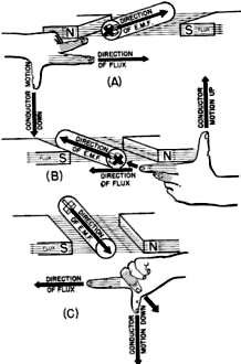
Figure 110. - Generator left hand rule.
It has been calculated that 100,000,000 lines of flux must be cut per second to produce
ONE volt. Now it's time to do a little mathematical thinking. If 100,000,000 lines cut
per second would produce one volt, then -200,000,000 lines cut per second would produce
two volts-and so on. In order to produce 10 volts, it would be necessary to cut 1,000,000,000
lines per second. The key to understanding this is in the term, PER SECOND. What , methods
can be used to cut more lines PER SECOND? There are three: (1) cut faster, which simply
means speeding up the moving conductor (2) put more lines there to be cut, which means
increasing the magnetic strength, or (3) cut with more than one conductor, that is, coil
the conductor so that many TURNS of wire cut the field.
Many generators employ the SPEED-UP principle to increase voltage output. This explains
the increased output of an automobile or a motor-launch generator when the engine is
raced.
The MAGNETIC FIELD STRENGTH can be increased by two methods - either increase the
current through the coil or put more turns on the electromagnet. Either method increases
the NI of the coil and you know that the magnetic strength of an electromagnet depends
on the number of ampere-turns.
When a CONDUCTOR IS COILED each turn is in series with the other turns. Therefore,
voltages add. Suppose one conductor cutting a field produces 10 volts. This same conductor,
coiled into 5 turns, and cutting the same field produces 50 volts.
MUTUAL INDUCTION
"Mutual" means that something. is shared. MUTUAL INDUCTION means that TWO circuits
share the energy of one. An example of mutual induction is pictured in figure 112. Coil
A is the PRIMARY circuit and gets its energy from the battery. Coil A changes the ELECTRICAL
energy of the battery into the MAGNETIC energy of a magnetic field. Then this field is
cut by coil B (the SECONDARY circuit), inducing a voltage. And the galvanometer registers
the current produced by the induced EMF.
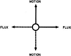
Figure 111. - Model for the generator hand rule.
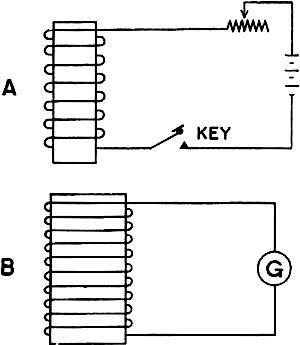
Figure 112. - Mutual induction circuits.
Here is an interesting fact - the induced voltage MIGHT have resulted from moving
coil B through the flux - but not NECESSARILY. When the switch to A was open, A had no
current and no field. But as soon as the switch was closed, current surged through the
coil and a field blossomed out. This moving field "breaks itself" across the wires of
coil B - thus lines are cut and a voltage is induced, WITHOUT MOVING COIL B. It only
takes a fraction of a second for the field to become STATIONARY at its maximum size -
cutting stops and induction ceases - the galvanometer returns to zero. If the switch
is opened, the field collapses back to the wires of coil A. Again the field breaks itself
across the wires of coil B. The galvanometer deflects, but in the opposite direction,
indicating that the induced voltage has reversed direction. The important point here
is that induction occurs only when the field is moving-either building up or collapsing.
This principle of holding the coils steady and forcing the field to move is used in all
MAKE-BREAK circuits. The spark coil and distributor points of a gasoline engine is a
make-break induction circuit.
Review the circuits of figure 112. Did you notice the rheostat R in the primary circuit?
When the switch to coil A is closed, the coil's current rises to its I = E/R value. The
field becomes stationary. But for any change in R, the current also changes. And for
every change in current, there is a corresponding field change. Suppose to be resistance
of the rheostat is decreased-current increases. The flux expands and cuts across coil
B inducing a voltage. Now suppose that the resistance of the rheostat is increased-the
current decreases. The flux contracts and again cuts across coil B inducing an opposite
voltage.
All of the examples used in connection with figure 112 illustrate MUTUAL INDUCTION.
You can always spot a mutual induction set-up by its TWO circuits. One circuit - the
primary - gets its energy from a voltage source (generator or battery) and the other
circuit - the secondary - gets its energy by induction from the field of the primary.
Two methods of mutual induction stand out -
(1) Move the secondary coil through the field of the primary coil.
(2) Cause the field of the primary to fluctuate, thus breaking it across
the conductors of the secondary.
LENZ'S LAW
There are four diagrams in figure 113. Each successive diagram adds to the complete
picture shown in D. The first diagram, A, shows a conductor at rest in a stationary magnetic
field. The second diagram, B, shows this conductor moving as a result of a downward push.
note that two items have been added - the downward push and the resulting induced current
in the conductor. ANY CONDUCTOR CARRYING current HAS A FIELD OF ITS OWN. This conductor
is no exception. The generator hand rule, proves this field to be in a counterclockwise
direction. The third diagram, C, shows the field of the conductor only. There are two
fields involved - the one from the MAGNET and the one from the CONDUCTOR. The first is
a straight line field traveling from the N pole to the S pole. The second is a circular
field surrounding the conductor.
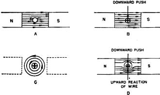
Figure 113. - Lenz's law.

Figure 114. - Conductor's and magnet's fields.
Magnetic lines never cross. Therefore, the lines of these two fields must either BLEND
together producing a STRONG resultant field or else they must CANCEL each other producing
a WEAK resultant field. A of figure 114 shows what happens above the wire. The two magnetic
fields are meeting head-on. It's like two autos meeting head-on - the forces cancel each
other. The cancellation of flux lines results in a WEAK field ABOVE the conductor.
B of figure 114 shows what happens below the wire. The two magnetic fields are blending
together. It's like two autos meeting front to rear - their forces add. This addition
of flux lines results in a STRONG and BENT field BELOW the conductor. There is a weak
field above and a strong bent field below the conductor. Remember that flux lines are
like rubber-bands - they tend to spring back into shape. But, before the distorted lines
below the conductor can spring back into shape, they must push the conductor up out of
the way. D of figure 113 shows ALL the conditions present during induction. Better review
them -
1. the DISTORTED FIELD resulting from the combination of the straight
field of the poles and the circular field of the conductor.
2. the DoWNWARD FORCE added by a push on the conductor.
3. the UPWARD FORCE which results from the distorted field. This upward
force opposes the downward push. Numbers 2 and 3 above are of prime importance.
They tell you that whenever you add a push to move a conductor in a magnetic field,
there is induced a current which sets up a field that tries to move the conductor back
against the push. This is Lenz's law -
IN ALL CASES OF ELECTROMAGNETIC INDUCTION, the DIRECTION OF the INDUCED EMF IS SUCH
THAT the MAGNETIC FIELD SET UP BY the RESULTING current TENDS TO STOP the MOTION PRODUCING
the EMF. Let's see what this means in everyday English.
Suppose you try to push a conductor UPWARD through a magnetic field. Immediately the
induced current sets up a field that tries to push the conductor DoWNWARD. The force
you use in the upward push must buck the magnetic downward push. If you push harder,
the conductor goes faster. But this only produces more induced current and a stronger
conductor field. Consequently, there is a stronger DoWNWARD force to buck your stronger
UPWARD force.
You might state Lenz's law this way - FOR EVERY FORCE THERE IS AN OPPOSITE FORCE SET
UP WHICH TENDS TO CANCEL the FIRST FORCE.
The whole business of Lenz's law is quite reasonable. Look at it this way. You want
to increase an induced voltage from 50 volts to 100 volts. In short, you want to double
the output. If you want TWICE as much output you're going to have to furnish twice as
much input. You'll have to push twice as hard against the conductor to get your 100 volts.
Have you ever heard a motor-driven welding generator? When the welding arc is struck
the motor whines and labors. Lenz's law is working. The arc increased the output load
and the motor is working against the increased opposing, force which was set up by the
increased load. The motor must increase its input to balance the increased output of
the arc.
SELF INDUCTION
There are only three items required to generate an induced voltage - (1) a conductor,
(2) a magnetic field, (3) motion between the conductor and the field. These three items
give you LINES OF FORCE CUT BY A CONDUCTOR. Look at figure 115 - are these three items
present in this circuit?
Conductors? - The coil has plenty of them. Magnetic
Field? - The coil sets it up whenever current flows. Motion? - Occurs
only when the field is moving.
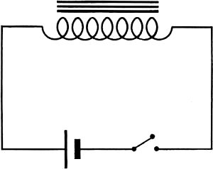
Figure 115. - Self induction circuits.
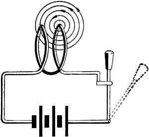
Figure 116. - Self induction in one turn.
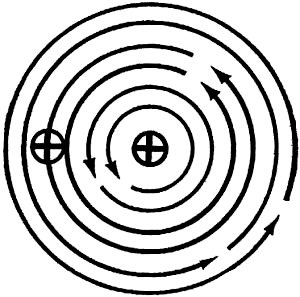
Figure 117. - Self induction - cross-section.
And to make the field move, you'll have to expand it or contract it by changing its
current. It's easy to make the coil induce a voltage in ITSELF by opening and closing
the switch. This kind of induction is called SELF INDUCTION. And here is how it works.
At the instant the switch is closed the current starts and magnetic lines expand from
the center of each conductor. As these lines blossom outward, they are cut by the other
conductors -of the coil. An EMF is induced in each conductor cutting flux.
Figure 116 shows an enlargement of only two turns of the coil in figure 115. Flux
is pictured blossoming out, from one of the turns. notice how these lines are cut by
the next turn. Now, applying the generator hand rule, determine the direction of the
induced voltage. It's easier to use the rule on a cross-section of the coil like figure
117. Flux direction is down (first finger). Motion is to the RIGHT (thumb). (ATTENTION
- the flux is moving across the conductor to the LEFT - the effect is AS THOUGH the CONDUCTOR
were moving to the RIGHT). Induced voltage is OUT (middle finger). It means exactly what
it says-the induced voltage OPPOSES the flow of current.
What happens when the switch is opened? The field collapses and cuts across the conductor
in the opposite direction. Because the direction of motion has reversed, the induced
EMF is now IN. Thus, in a collapsing field, the induced EMF AIDS the flow of current.
These are the characteristics of self-induction -
1. Any coil will induce a voltage in itself whenever its current value
exchanges because current controls the size and strength of the field.
2. When the current is increasing (field expanding), the induced EMF
opposes current flow.
3. When the current is decreasing (field contracting) , the induced EMF
aids the current flow.
This, after all, is another manifestation of Lenz's law. The first force is applied
voltage (from a battery). The second force is the induced voltage. The induced voltage
opposes the applied when the current is increasing and aids the applied when the current
is decreasing. Thus the induced voltage opposes any changes in the current value.
The voltage of self induction can be very troublesome. Imagine that you are operating
the switch controlling the field coils on a large motor. These coils have thousands of
turns. When the switch is closed, the voltage of self induction does little damage. It
opposes the increase of current flow for an instant (perhaps 0.1 second), but as soon
as the field is built up and stationary, the induced voltage ceases. On the other hand,
when the switch is opened, the field rapidly contracts. The induced voltage on collapse
may be hundreds of times as strong as the applied voltage. This tremendous induced voltage
drives current across the opening switch terminals in the form of an arc - it CAN burn
both the operator and the switch very badly. All switches subject to high induced voltages
are protected by discharge rheostats to absorb and dissipate the induced voltage, which
might otherwise cause dangerous arcs.
So far in this book, current has been understood as a STEADY flow of electrons. Apply
a voltage - it pushes steadily - current flows in a steady stream of electrons. Technically,
this type of current is known as DIRECT current (D.C.).

Figure 118. - Pulsating d.c.
Telephones, ignition coils, and radios make use of a special type of direct current.
By means of rheostats, or make-break switches, the current is alternately turned on and
off. This results in a PULSATING D.C. Pulsating d.c. is like the blood in your body.
The blood gets a push (or pulsation) every time your heart beats. In a circuit this means
that the current flows in SURGES. The surges may be all of the same strength and regularly
spaced, or they may be of varying strength and irregularly spaced. The exact type of
pulsating d.c. depends on the electrical machinery producing the pulsations. Figure 118
is two graphs of pulsating d.c. A is the current in a gasoline engine ignition coil.
It is regular and the surges are of equal strength. B is the current in a telephone circuit.
It is irregular and the surges are unequal.
When pulsating d.c. is fed into a coil, its magnetic field does some tricky things.
Every time the current goes up the field expands, and every time the current goes down
the field contracts. In short, the field is almost constantly in MOTION. And moving fields
produce a lot of induced voltage. Pulsating d.c. produces a field like that of a closing
and opening circuit switch - ONLY - it is much more rapid.
In mutual induction, if the primary is energized with pulsating d.c., the secondary
is alternately cut by the expanding and contracting flux. This produces a high induced
voltage on the secondary coil. In the gasoline engine ignition coil, pictured in figure
119, the primary circuit is energized from a 6-volt battery through the make-break switch
of the distributor points. When the points close the flux field expands, and when the
points open, the field rapidly collapses. This collapse is so rapid that the induced
voltage in the secondary is often 20,000 VOLTS. This high voltage is used in jumping
current across the air gap at the spark plugs. If you've ever inadvertently taken the
"poke" off a spark plug you know it's plenty hot!
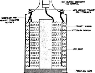
Figure 119. - Gasoline engine ignition coil.
In self induction, a coil carrying pulsating d.c. is a confusing mixture of current
values, applied voltage values, and induced voltage values. Simplified, it's like this-when
the current is on the increase, the voltage of self induction opposes the applied voltage.
This makes the net voltage (applied minus induced) low and the current is slow, in building
up. But on collapse - the field cuts in the opposite direction and the induced voltage
aids the applied. This makes the net voltage high and produces a surge of current. Surging
current is dangerous and must be guarded against with shields, insulators, and resistors.
The ordinary coils of a small electrical motor may produce one or two thousand volts
of self induction if their feeder circuit is opened rapidly.
ALTERNATING current
Direct current, either pulsating or regular, is a ONE WAY flow of electrons. A TWO
WAY flow of electrons - a current which first flows in one direction and then reverses
and flows in the opposite direction - is an ALTERNATING current (A.C.).
Alternating current voltage cannot be obtained directly from batteries, but usually
originates in a special kind of generator called an ALTERNATOR. The alternator starts
out with a zero voltage. It then builds up a voltage which pushes in the POSITIVE DIRECTION.
This positive voltage increases until the maximum is reached, then decreases again to
a zero value. The voltage then builds up again to a maximum value, but in the NEGATIVE
DIRECTION, then decreases to zero. The period of time required to go from zero, to positive
maxi-mum, to zero, to negative maximum and again to zero is called a CYCLE. And the number
of cycles occurring per second is the FREQUENCY.
Figure 120 is a graph of one cycle-of a.c. voltage. In this graph the voltage strength
is measured on the ordinate and the time of one cycle is measured on the abscissa. Point
1 is the beginning of the cycle-zero voltage. From point 1 to point 2, the voltage steadily
increases from 0 to 10 to 20 to 30 to 40 to 50 to 60 volts. Point 2 is the positive maximum
(60 v.). Between points 2 and 3 the voltage decreases to zero in the same steady fashion
that it built up. From point 3 to point 4 the voltage rises again, but in the negative
direction. Point 4 is the negative maximum - again 60 volts. Between points 4 and 5,
the voltage falls back to zero. Usually a cycle takes a lot less time to happen than
to tell about - normally about 1/60th of a second. A cycle takes 1/60th of a second when
the frequency equals 60 - because a frequency of 60 means 60 cycles per second. Ohm's
law tells you that the current varies and changes direction exactly the same as the voltage.
For every instant there is an I = E/R value of current. The I changes. in exact proportion
to every change of E.

Figure 120. - Graph of a.c. voltage.
SUMMARY OF A.C. AND D.C. INDUCTION
| ACTION |
D.C. |
PULSATING D.C. |
A.C. |
| current direction |
Always in one direction. |
Always in one direction. |
Changes direction regularly. |
| current steadiness |
Always steady. |
Rises and falls. |
Rises and falls. |
| Magnetic fields produced |
Build up-then steady as long as current is steady. Always the same direction. |
Constantly expanding and contracting. Always the same direction. |
Constantly expanding and contracting. Reverse direction regularly. |
| Mutual induction |
Occurs only when circuit is opened, closed, or when current value changes. Induced
volt-age varies in direction depending on primary current. |
Occurs constantly. Varies in direction constantly. |
Occurs constantly. Varies in direction constantly. |
| Self induction |
Occurs only when circuit is open or closed or when current value changes. Varies
in direction. |
Occurs constantly. Varies in direction. |
Occurs constantly. Varies in direction. |
HOW A.C. ACTS IN INDUCTION
Alternating current is constantly changing value and direction. Therefore, the fields
produced by a.c. are constantly expanding and contracting - also constantly reversing
polarity. In mutual induction, a.c. on the primary produces a CONTINUOUS a.c. on
the secondary. The TRANSFORMER is an a.c. mutual induction circuit.
In self induction, a.c. produces a CONTINUOUS voltage. The INDUCED voltage opposes
the APPLIED and some coils are designed so that the EMF of self induction is strong enough
to almost completely stop current flow. COMPARISON OF A.C. AND D.C.
The table on page 171 compares the action of a.c., pulsating d.c., and regular d.c.
in mutual and self induction. Study it-if there are points you don't understand, go back
over this chapter and get 'em cleared up.
Chapter 13 Quiz
(click
here)
|


