Search RFC: |                                     
Please support my efforts by advertising!
About | Sitemap | Homepage Archive
Serving a Pleasant Blend of Yesterday, Today, and Tomorrow™
Vintage Magazines
Electronics World
Popular Electronics
Radio & TV News
QST | Pop Science
Popular Mechanics
Radio-Craft
Radio-Electronics
Short Wave Craft
Electronics | OFA
Saturday Eve Post
Please Support My Advertisers!

Aegis Power | Centric RF | RFCT
Alliance Test | Empower RF
Isotec | Reactel | SF Circuits

Formulas & Data

Electronics | RF
Mathematics
Mechanics | Physics


Calvin & Phineas

Resources

Articles, Forums, Radar
Magazines, Museum
Radio Service Data
Software, Videos


Artificial Intelligence

Entertainment

Crosswords, Humor Cogitations, Podcast
Quotes, Quizzes

Parts & Services

1000s of Listings

        Software:

Please DONATE

RF Cascade Workbook | RF Symbols for Office
RF Symbols for Visio | RF Stencils for Visio
Espresso Engineering WorkbookCafe Press
Innovative Power Products Cool Chip Thermal Dissipation

EIA Vacuum-Tube Base Diagrams

Base diagrams correspond to the codes in "Base" columns of the tube-data tables. Bottom views are shown throughout. Base connections are abbreviated as follows:

BS - Base Sleeve               NC - No Connection

F - Filament                        P - Plate

G - Grid PB                         F - Beam Plates

H- Heater                           S - Shell

IC - Internal Connection    K - Cathode


Alphabetical subscripts indicate structures in multistructure tubes.

D = diode, P = pentode, T = triode, HX = hexode

Subscript CT indicates filament or heater center tap.

Generally, when Pin 1 of a metal-envelope tube (except all triodes) is shown connected to the envelope, Pin 1 of a glass-envelope counterpart (suffix G or GT) is connected to an internal shield.

Related Pages on RF Cafe

- Tube Base Diagrams

- A Course in Radio Fundamentals-Vacuum Tubes

     Sep 1942 QST

- Electrons on Parade

     Tube Production Video by RCA c.1942

- NEETS Module 6 - Vacuum Tubes

- Vacuum Tube Vendors

Click here to order these tube bases in

   Visio format!

Virtual Valve Website

• The complete 1951 Sylvania Tube Catalog (15MB)

• Here are tube socket dimensioned drawings.

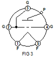
 FIG EIA Vacuum-Tube Base Diagrams - RF Cafe 3G EIA Vacuum-Tube Base Diagrams - RF Cafe 5AW EIA Vacuum-Tube Base Diagrams - RF Cafe 5AZ EIA Vacuum-Tube Base Diagrams - RF Cafe 5BA EIA Vacuum-Tube Base Diagrams - RF Cafe
5BK EIA Vacuum-Tube Base Diagrams - RF Cafe 6AM EIA Vacuum-Tube Base Diagrams - RF Cafe 7CK EIA Vacuum-Tube Base Diagrams - RF Cafe 8JC EIA Vacuum-Tube Base Diagrams - RF Cafe 8JX EIA Vacuum-Tube Base Diagrams - RF Cafe
9NM EIA Vacuum-Tube Base Diagrams - RF Cafe 9QL EIA Vacuum-Tube Base Diagrams - RF Cafe 9QU EIA Vacuum-Tube Base Diagrams - RF Cafe FIG 11EIA Vacuum-Tube Base Diagrams - RF Cafe 12FB EIA Vacuum-Tube Base Diagrams - RF Cafe
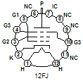
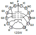
12FJ EIA Vacuum-Tube Base Diagrams - RF Cafe 12FK EIA Vacuum-Tube Base Diagrams - RF Cafe 12FY EIA Vacuum-Tube Base Diagrams - RF Cafe 12GJ EIA Vacuum-Tube Base Diagrams - RF Cafe 12GW EIA Vacuum-Tube Base Diagrams - RF Cafe
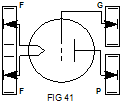
12HL EIA Vacuum-Tube Base Diagrams - RF Cafe FIG 21 EIA Vacuum-Tube Base Diagrams - RF Cafe FIG 41 EIA Vacuum-Tube Base Diagrams - RF Cafe FIG 87EIA Vacuum-Tube Base Diagrams - RF Cafe These tube bases are derived from the 2001 ARRL Handbook.

"Tube Bases for Visio" Copyrighted by RF Cafe 2003

Innovative Power Products Cool Chip Thermal Dissipation